Continue to Site

Eng-Tips is the largest engineering community on the Internet

Intelligent Work Forums for Engineering Professionals

  • Congratulations KootK on being selected by the Eng-Tips community for having the most helpful posts in the forums last week. Way to Go!

How you read this drawing?

Status
Not open for further replies.

Kedu

Mechanical
May 9, 2017
193
I've always been under the impression that if the drawing creator missplaced the datum feature symbol for a cylindrical surface, the datum is still the axis (yes, even the datum feature symbol is not aligned with the size dimensions, AGAIN, on a cylindrical feature and not on a width/ tab).

Anyone else seeing this otherwise?
I will learn from anyone.

Again, as I stated before, for me if someone misplaced the datum FEATURE SYMBOL on a cylindrical surface (not on a width or tab) I will interpret it just as I stated, A MISSPLACEMENT and NOT that the datum is now a plane (or a line) instead of the axis.

opposite opinions are welcomed and encouraged.
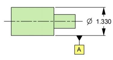
DTP_-_Copy_ysunrn.jpg
 
Replies continue below

Recommended for you

Woosang -- for the most part I agree. But the language does leave some wiggle room. It simply boils down to this: When a datum feature symbol is attached in ANY way to a cylindrical object, and does not employ datum targets, then wouldn't the datum have to be the axis?

John-Paul Belanger
Certified Sr. GD&T Professional
Geometric Learning Systems
 
J-P,

Belanger said:
When a datum feature symbol is attached in ANY way to a cylindrical object, and does not employ datum targets, then wouldn't the datum have to be the axis?

Looks like Tec-Ease said NO, it does not have to be the datum axis! Could be "datum plane" and a "line in datum plane"

Go figure!

 
greenimi -- that was discussed above. They are not showing a good example. If they want a "datum plane" and a "line in datum plane" then they should have used a datum target.

John-Paul Belanger
Certified Sr. GD&T Professional
Geometric Learning Systems
 
Either way, it's difficult these days to find engineers/machinists/inspectors that understand GD&T anyway.
I have to use less of it for this reason. I get into arguments all the time because they want to remove it. They think it costs $ more with it.
Frustrating.

ctopher, CSWP
SolidWorks '17
ctophers home
SolidWorks Legion
 
ctopher,
Do you feel that the situation used to be better in past years?
 
JP,

Thats the next sentence of the tip.

tec-ease said:
In the view below, because the datum target feature is offset from the size dimension line, the datum may be interpreted as a line lying in a plane tangent to the feature indicated. If line contact is desired a datum target line should be indicated.

To me, it doesn't seem like they're arguing a tangent plane would be a valid interpretation - only that its possible that someone could interpret it that way and to avoid placing your datum feature symbol in such a manner. Hence the statement about datum targets. You would get my full agreement that such a specification as shown (without a datum target line) is absolutely not a valid way to specify a tangent plane/datum line.

Not trying to hold your feet to the fire on a topic discussed a long time ago ( but I agree with what you said in that thread "just make sure the drawing is clear". I would not say that the notation shown in the OP/tec-ease tip is clear - the fact that this discussion keeps coming up (and I've seen other questions on here about it, one I believe where the OP actually intended to derive a tangent plane) tells me as much.
 
I see the issue now. Yes, ambiguous, at least at a technical level.

I don't think I've ever used a silhouette as a datum.
 
I don't recall a Y14.5 standard example of finding the tangent to a surface and using it as a datum target.
 
Status
Not open for further replies.

Part and Inventory Search

Sponsor