Continue to Site

Eng-Tips is the largest engineering community on the Internet

Intelligent Work Forums for Engineering Professionals

  • Congratulations SSS148 on being selected by the Eng-Tips community for having the most helpful posts in the forums last week. Way to Go!

HSS Beam to WF Column Web 3

Status
Not open for further replies.

waytsh

Structural
Jun 10, 2004
373
I know this topic has been covered in a number of threads but my condition is a little different from those I have found. Let me give a quick break down of my situation.

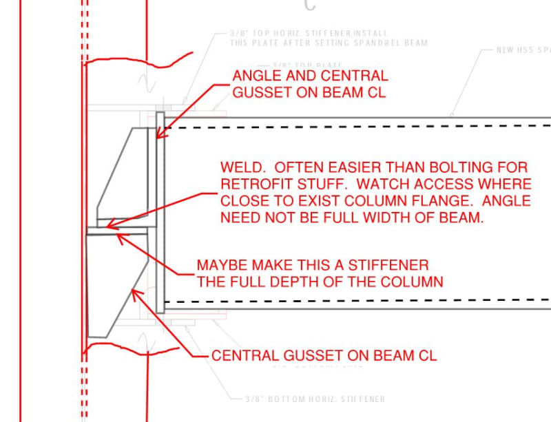
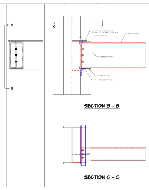
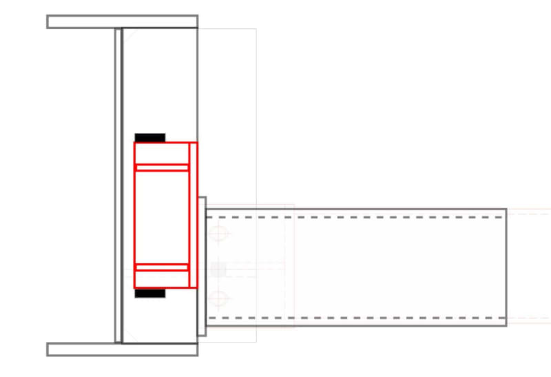
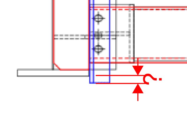
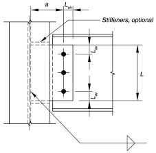
1) I have an HSS spandreal that will connect to the web of a WF column.

2) The connection to the column must be designed to resist both vertical and horizontal shear as well as torsion.

3) The connection cannot induce moment into the weak axis of the column.

4) Forces are not very large, 2.2 kips vertical, 2.0 kips horizontal, and 16.3 kip-in of torsion.

5) The design of the HSS section is controlled by deflection since it is over a glass wall and is the reason the size is so large and the forces are so small.

I am considering the connection shown below but it is very complicated and is a two step process. I welcome any better solutions. I am trying to avoid a bolted end-plate due to its tendency to put moment into the weak axis of the column and the fact that the length of the HSS will need to be perfect.

Thank you

[URL unfurl="true"]https://res.cloudinary.com/engineering-com/image/upload/v1582057747/tips/HSS_Connection_Concept_k2ilua.pdf[/url]
 
Replies continue below

Recommended for you

So the top and bottom horizontal stiffener plates are there to resist torsion and horizontal load? And they're not welded to the top and bottom plates?
 
Same condition both ends? This affects fit up.

The columns are existing, right?

Can your connection project 1/2 or so outside of the flanges?
 
stiffeners between flanges to match HSS height.

Seat angle welded full width of column at bottom, smaller restraining angle welded full width of column welded only at the toes to prevent restraint.

Probably should align the seat angles with the stiffeners rather than matching the stiffeners to the HSS height, in order to transfer the horiz shear into them. Also, if its not implied, extend the angles 1/2 inch beyond the WF col flanges for the fillet welds ea end.
 
Keep an eye out for fit-up and weld access issues. This is not the most direct torsion path but, then, it's also not much torsion.

c01_x5rbeq.jpg
 
Azcats: Yes the top and bottom stiffeners would resist the horizontal loading and the torsion. I was not planning to weld them to the top and bottom plates but rather bolt through a short slot to keep from fixing the connection in the strong axis.

KootK: Yes, this condition would be on both ends of the beam. That is why I am planning to only weld the top horizontal stiffener in place after the HSS spandrel has been set. Correct, columns are existing. Not sure what you mean about projecting 1/2" past the flanges. Right now the centerline of the bolts are 1" past the tips of the flanges so that the erector can reach down from the top to install the vertical shear tab bolts.

Boiler106: I don't quite follow. Could you throw together a sketch when you get the chance?
 
KootK, I hadn't seen your last message before sending mine. Interesting idea.
 
given the relatively light loads, i prefer the simplicity of this one:

1_drm6ze.png
 
waytish said:
Interesting idea.

Is that like "interesting thanks for coming out KootK" or "I'm gonna do this and send you a check for $50 KootK"?

For something like this, I consider any shop side fabrication to be essentially free. It's all about how easy it is to install in the field.

If there's a weld access issue, I was thinking that it might be dealt with as shown below.

I'd not be terribly worried about weak axis column moments. Given the realtive stiffness of the beam strong axis vs the column weak axis, I suspect that the beam would actually rotationally brace the column in the event of an accidental moment connection. I still like an end plate connection into the web with one major concern: fit-up. If you could get it in there with shim plates though, I think that would be ideal from a mechanical perspective.

c02_xljkam.jpg
 
Ah, now I follow. You were thinking to eliminate the vertical clip as well and take all the vertical load into the bottom seat, right?

On a different note, how are you guys embedding the pictures right into the conversation like that?
 
waytish said:
On a different note, how are you guys embedding the pictures right into the conversation like that?

Take a screen shot snip and save it someplace as JPG etc. Then use the little camera button in the ribbon right above the window that you type into.
 
Haha, I'm too slow KootK and you keep slipping your comments in ahead of me. I agree with what you are saying about the end plate connection. I would love to be able to do that but what I am not showing here is that I will have multiple locations where this connection will be back to back so that complicates erection a bit as well. I must admit I think I am leaning towards Boilers concept at this point. I might have to dwell on it this evening.
 
waytish said:
Not sure what you mean about projecting 1/2" past the flanges.

This. I was basically asking if something like Boiler106 suggested was spatially possible. I imagine there's a wall someplace.

c03_kzuxs7.jpg
 
You got me again. Thanks for the info!
 
There will be a light gauge vertical stud wall. They would need to make sure that their studs do not land at the location of the angles.
 
waytish said:
I would love to be able to do that but what I am not showing here is that I will have multiple locations where this connection will be back to back so that complicates erection a bit as well.

As in both ends will have this connection? That's what I was getting at with fit-up. To use my detail, you'd have to check that you could feed it in at an angle and drop it vertically.

I like Boiler106's detail too. However, I was trying to stay true to your zero weak axis moment connection requirement. Both Boiler106's detail, and your original detail, would induce weak axis column moment and column torsion based on an eccentricity slightly greater than half of the column width. For small-ish loads, I'd be inclined to just ask the column to deal with those eccentricities. But, then, it's your baby.

Or were you only concerned about potential moments arising from a strong axis moment connection between the beam and column?
 

KootK said:
As in both ends will have this connection?

As in on both sides of the column, but it will also be on both ends of the beam as well except for a couple locations where it will connect to a column flange on one side.

KootK said:
Or were you only concerned about potential moments arising from a strong axis moment connection between the beam and column?

Yes, this was my concern. The column can deal with the eccentricity of the connection. However, your concept is good for reducing the impact of the eccentricity.

Thank you for all the responses.
 
KootK said:
I don't get it, how does that complicate beam erection?

I guess it doesn't all that much. We would just need to add a beam seat to hold the beam on one side in place until the other is lifted so everything can be bolted together through the web. ...or extend the end-plate on one side and add a couple erection bolts to the splice.
 
just wanted to make a quick point: the eccentric loading is 2kip vertical located say 2 inches beyond the face of the column which would be similar to any simple gravity connection and is no where close to the moment capacity of the column. keep in mind this is a VERY lightly loaded connection.

As for restraining or developing end moments in the HSS, with the proper weld detailing and angle selection, you can allow the top restraint angle to flex much like the seat angle connection details in the AISC manual, which would release weak axis moments.

while i appreciate kootk's detail, its complicated by the fact you have to get the lug in between the flanges during erection. this is the main driver of going towards extended single plate connections at column webs (see below)

1_tadzzj.png
 
Status
Not open for further replies.

Part and Inventory Search

Sponsor