Continue to Site

Eng-Tips is the largest engineering community on the Internet

Intelligent Work Forums for Engineering Professionals

  • Congratulations SSS148 on being selected by the Eng-Tips community for having the most helpful posts in the forums last week. Way to Go!

HSS Beam to WF Column Web 3

Status
Not open for further replies.

waytsh

Structural
Jun 10, 2004
373
I know this topic has been covered in a number of threads but my condition is a little different from those I have found. Let me give a quick break down of my situation.

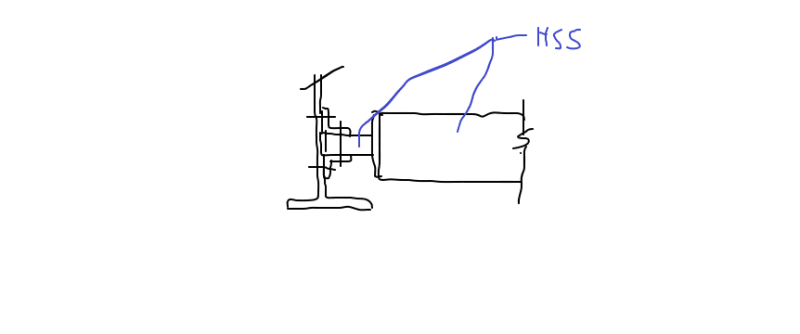
1) I have an HSS spandreal that will connect to the web of a WF column.

2) The connection to the column must be designed to resist both vertical and horizontal shear as well as torsion.

3) The connection cannot induce moment into the weak axis of the column.

4) Forces are not very large, 2.2 kips vertical, 2.0 kips horizontal, and 16.3 kip-in of torsion.

5) The design of the HSS section is controlled by deflection since it is over a glass wall and is the reason the size is so large and the forces are so small.

I am considering the connection shown below but it is very complicated and is a two step process. I welcome any better solutions. I am trying to avoid a bolted end-plate due to its tendency to put moment into the weak axis of the column and the fact that the length of the HSS will need to be perfect.

Thank you

[URL unfurl="true"]https://res.cloudinary.com/engineering-com/image/upload/v1582057747/tips/HSS_Connection_Concept_k2ilua.pdf[/url]
 
Replies continue below

Recommended for you

Not too worry, I like your detail better too now that I fully understand OP's priorities and constraints.

Boiler106 said:
As for restraining or developing end moments in the HSS, with the proper weld detailing and angle selection, you can allow the top restraint angle to flex much like the seat angle connection details in the AISC manual, which would release weak axis moments.

1) I'm not sure that you'll be able to accomplish that flexibility when it comes down to the nuts a bolts of how you'll actually attach the topside angle to the column flanges. It might take slotted bolt holes in the horizontal angle leg to get the job done.

2) I think that moment connecting the beam to the column might reduce the column moments below those induced by the load eccentricity. The beam is very stiff, by design, and the column is not. I don't necessarily share the view that one needs to run from fixity here.
 
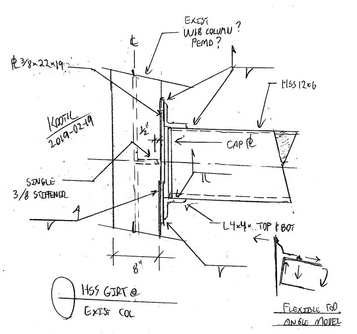
Another take on Boiler's concept, trying to achieve the flexible angle thing at the top.

- the large plate feels a bit overkill. On the other hand, ond less stiffeners saves much more money than the plate material would cost.

- I don't know of a ready method for seat angle design when the angle is mounted to something flexible. I'm not too worried about that given the light loads though.

- My gut feel is that this would be fine with no stiffener in the column. The sketches kind of suggest a built up column like a PEMB frame or something though. I'd feel better about going without stiffeners if it were a rolled section with a stocky web/flange intersection.

c01_kmyns9.jpg
 
not to drag this out (no pun intended) but according to conventional AISC seat angle design, flexibility of the angle is only required on the top restraint angle.

 
KootK said:
The sketches kind of suggest a built up column like a PEMB frame or something though

These are actually built-up columns. For simplicity I just referred to them as WF in the title to indicate the shape.

I think we are heading in the right direction here. Certainly much simpler than what I had drawn up originally. Thanks again for all the suggestions and the effort spent!
 
Boiler06 said:
...according to conventional AISC seat angle design, flexibility of the angle is only required on the top restraint angle.

If you're referring to my last post, I wasn't discussing the flexibility of the seat angle. Rather, I was discussing the flexibility of whatever torsionally supports the seat angle with respect to twist. The canned seat angle design methodology in the AISC manual assumes that restraint is coming from something stiff like a strong axis column etc. In the case of your original detail, that torsional restraint is provided by the angle itself acting in torsion along its length (I think).

It's not that the twist can't be resolved other ways, it most definitely can. Those other ways just won't be found nicely tabulated in the AISC manual. For something of this scale I would probably design the seat angle as a flexural extension of the beam and deal with it that way.

c01_komogf.jpg
 
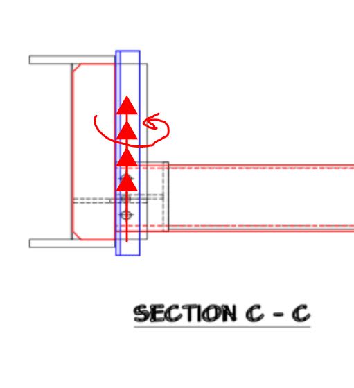
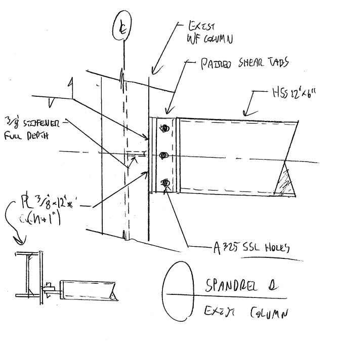
I've got one more trick up my sleeve. Yeah, this isn't exactly Blodgett worthy as far as lateral shear and torsion delivery go. That said, this kind of thing is done all the time for for light loads like we're considering here.

c01_qzposp.jpg
 
KootK, I had actually considered something like this early on but shied away from it from it because I wasn't sure how to check the shear tab for the combined vertical load, weak axis bending, and torsion. Like you said these loads are light and my intuition is any reasonable thickness will check out but I just need to prove it.
 
There have been a number of threads here about how to "prove" this situation. And I've contributed to several. Hopefully you can track one or more of those down. 3/8" tabs with 5/16 fillet weld each side.
 
I'll do some research on that and see that I can find, thanks.
 
What is the size of HSS, and the clear distance between its wall and the column flange? I am trying to see if we can fit something in between two vertical angles.
 
If the column is deep and the HSS is 12x6, can you not use an end plate connection to the HSS with fillet welds all around, and simply bolt the end plate to the column web with an eccentric connection if you have clearance to put the member in place? maybe use 1" shims if necessary?

Dik
 
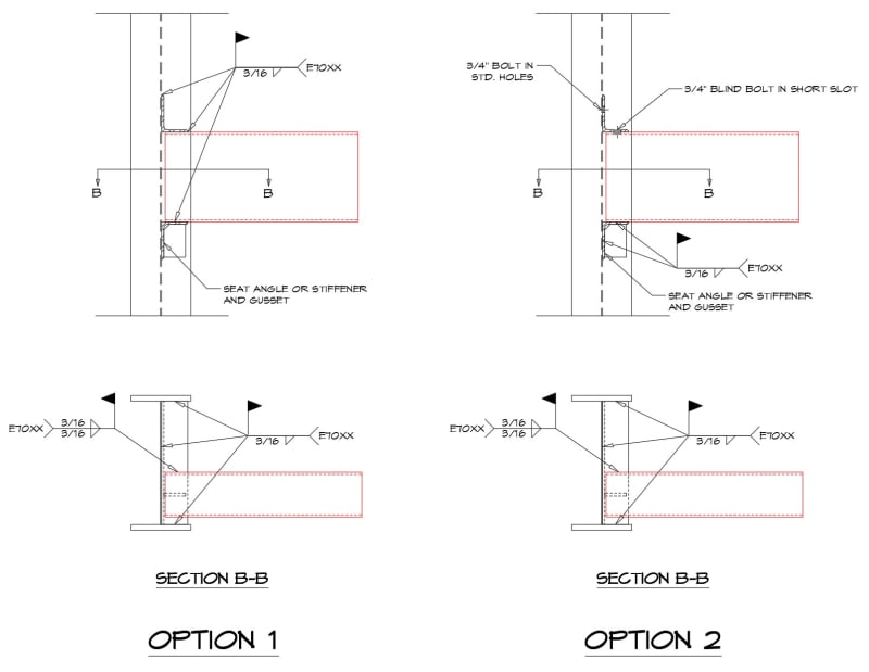
What if I use a little bit of all of these great ideas and push the seat angle in to the web of the column and use a welded or bolted top angle clip? Something like this...

HSS_Connection_Options_osvrb0.jpg
 
Another idea, if possible (spacing, strength).

R_nssfv1.png
 
1) Are you confident that you'll be able to feed the HSS inside the flanges like that without field fit-up issues? I thought that was one of our design constraints.

2) I'm pretty sure that you could get away without the vertical stiffener. Not that it's hurting anything.

3) There may not be access enough to be able to weld the HSS to the seat angle on the side closest to the column flange. This might force you into an overhead weld to connect the seat angle to the HSS.

4) With the bolted top clip option, keep in mind that you'll be doing this from both sides. Sometimes it can be difficult to align incoming parts on both sides of the web for bolting. Maybe you can address this by slotting the column bolt holes horizontally and the angle bolt holes vertically. Or maybe it's not really a big deal, I'm not sure.
 
KootK said:
Are you confident that you'll be able to feed the HSS inside the flanges like that without field fit-up issues?

I am not, I would need to verify with the erector.

KootK said:
There may not be access enough to be able to weld the HSS to the seat angle on the side closest to the column flange. This might force you into an overhead weld to connect the seat angle to the HSS.

Good point. I suppose I could look at blind bolting the bottom as well.

KootK said:
With the bolted top clip option, keep in mind that you'll be doing this from both sides. Sometimes it can be difficult to align incoming parts on both sides of the web for bolting. Maybe you can address this by slotting the column bolt holes horizontally and the angle bolt holes vertically. Or maybe it's not really a big deal, I'm not sure.

I am not sure how big of a deal this is either. I would not have thought this would be any more of a problem than a typical back-to-back double angle connection but I could be wrong.

retired13 - Keep in mind this connection has weak axis shear and torsion as well. I know the double angles and shear tab can handle some but I would need to quantify it.

Thanks for the comments.
 
Sorry for my over-simplification. If the angles and HSS extension are stiff enough (need quantify), the shear force in a single bolt on the column web should be equal to V/n + M/2d, in which n is number of bolts, d is the lever arm, 2 represents only the top and bottommost bolts are engaged in torsion. This would work only with a space that allows hand access, and a HSS extension adequate to resist torsion.

You may need slot holes, or over sized holes to solve problem in fitting. Also, you can consider install the beam with one angle attached for temporary support, then install and fasten the other. It might alleviate some headaches during erection.
 
Status
Not open for further replies.

Part and Inventory Search

Sponsor