Continue to Site

Eng-Tips is the largest engineering community on the Internet

Intelligent Work Forums for Engineering Professionals

  • Congratulations KootK on being selected by the Eng-Tips community for having the most helpful posts in the forums last week. Way to Go!

HSS Column Connection to Bottom of HSS Rafter 3

Status
Not open for further replies.

waytsh

Structural
Jun 10, 2004
371
Hi All,

I am working on a project where I would like to use the following column to rafter connection on an HSS frame:
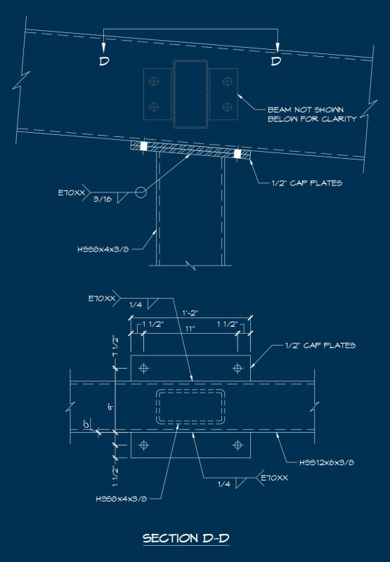
HSS_Column_to_HSS_Rafter_Connection_dmyipe.jpg


Does anyone know of references that address this type of condition? The column side is nothing really unusual, it is more the rafter side of the splice that is a little different. Checking the welds and concentrated flange loads on the rafter should be pretty straightforward. Plate thickness should not be controlled on the rafter side. What else am I missing?

Before you say it I know a direct weld would be better. There is a chance I can talk the owner into that but it will make transport a little tricky.

Look forward to hearing your thoughts. Thanks in advance!
 
Replies continue below

Recommended for you

I can't see any problems with it, but in my mind that is probably not a (very) rigid connection and I would treat it as a pinned connection.

Not sure what your assumption was?
 
I had assumed pinned but also did a run as fixed just to make sure the surrounding members could handle any moment that might be drawn in with that type of connection.
 
Waytsh:
For starters, there just isn’t a ref. book, a code para. and formula, or a worked example, or a guide book for every possible detail and condition in the universe. Although, the code and guide publishers are working on that, as long as we are willing to keep paying for their perpetual additions to the codes and cook books for structural engineering. These are not all improvements to the engineering process, but they do keep their publishing industry profitable. Then we won’t have to do any more actual engineering thinking, no experience or judgement needed, just find the right example ref. detail, and call it out on the drwg. Your detail looks o.k. to me. I like the cap pls., as apposed to direct welding of the col. to the rafter. Those pls. give you a better chance to distribute the col. loads from the col. webs and out into the webs of the rafters through the .25” fillet welds. Except they are not fillets, they are flare-bevel-groove welds to the HSS 12x6. And, get rid of the dimension slash mark near the 9” width dim.
 
Other than the 1/2" plates and the 3/16" fillet welds, the connection can be pretty rigid.

Rather than think climate change and the corona virus as science, think of it as the wrath of God. Feel any better?

-Dik
 
dhengr, yes, I understand there is not a reference for every possible detail and I am not advocating for that. However, if this has been addressed already and there is relevant information out there, I am going to take advantage of it. Good point about the flare-bevel welds. I didn't really flesh out this detail yet, just kind of threw it together to help me visualize the situation and there are some artifacts from the original detail. I will clean it up when I start nailing it down. Thanks.

For those interested it turns out the Steel Tube Institute, HSS Design Manual, Vol. 3 Connections at HSS Members covers this condition.
 
your bolt positions make it seem like you want to it to have some fixity
 
I will probably end up reducing the 11" spacing.
 
chapter K in AISC manual has some design checks for cap plate but it has a fin

i agree your design has some sort of positive support independent of the bolts
versus a fin design

and plastification can be a thing for the fin (longitudinal plate) on the beam

but the shear plate will more guarantee your pin
 
I should note that there is also weak axis shear on this connection.
 
waytsh said:
I should note that there is also weak axis shear...
oh right the transparent beam
you only have weld in one direction though for the rafter to plate
also are you bolting through the hss for that secondary? beam?

oh i just checked back on the cap plate equations it seems like it just converges
to Fy*A when load width is larger than column itself

check example k-11 from the aisc design examples i think v14
was removed in v15 not sure why
 
wrxsti said:
you only have weld in one direction though for the rafter to plate

I will be adding a transverse weld across the bottom of the rafter as well.

wrxsti said:
also are you bolting through the hss for that secondary? beam?

Yes, I will be through bolting for the spandrel beam connection.

wrxsti said:
check example k-11 from the aisc design examples

Will do, thanks.
 
Dik said:
Other than the 1/2" plates and the 3/16" fillet welds, the connection can be pretty rigid.

Agree.

Also, if all you need is a pin then 2 bolts central is enough.
 
One of my early real world lessons on site was when an engineer designed a "pin connection" like this for rafters supported by relatively light HSS. The HSS columns ended up looking like bananas when the the connection didn't behave like a pin. In my example column's stiffness is relative to the rafter was significantly lower than the example shown here.

Still, if this connection is mean to be pinned I then wonder why rectangular hollow section is being used rather than square.
 
Thanks, I will use 2 bolts to avoid my column ended up like a banana. [glasses]
 
human909 said:
Still, if this connection is mean to be pinned I then wonder why rectangular hollow section is being used rather than square.

There is more lateral load parallel to the frame than perpendicular. Lateral loads are being resisted with double angle kickers that attach below where the detail I showed ends. So the point load from the kicker is higher in that direction than normal to the frame.
 
Status
Not open for further replies.

Part and Inventory Search

Sponsor