Eng-Tips is the largest engineering community on the Internet

Intelligent Work Forums for Engineering Professionals

HSS column design with shear plate connection

Status
Not open for further replies.

BAGW

Structural
Jul 15, 2015
388
0
16
US
Hi,

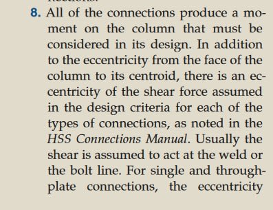
When the beam/girders are attached to HSS tube with shear plate connection, should the column be designed for eccentricity from the bolt to center line of column?

Can we get away from designing the column from eccentric moment if we design the connection for the eccentricity? Similar to extended shear tab connection?
 
Replies continue below

Recommended for you

The AISC Manual Part 10 talks about this. In the 16th ed., see the discussion starting on Page 10-96.

For punching shear, e is from the face of HSS to centroid of bolt group.

For the bolts, plate, etc. the eccentricities for Single Plate Shear Connections, starting on Page 10-49, should be used. "a" is the distance from HSS wall to first vertical row of bolts. For conventional, the eccentricity will be a/2 or a from Table 10-9. For extended, the eccentricity is a.
 
In the 15th edition, page 10-95 'The design procedure for extended single plate shear connections permits the column to be designed for an axial force without eccentricity'

Edit: sorry I realize this is for W-shapes. I take the discussion at the top of 10-155 to mean that the same thing applies to HSS columns.
 
This is only an issue where there is framing on one side of the column, not both. I believe most engineers would ignore the eccentricity between face of tube and centerline of tube, and design the column for axial load only. One could argue the same thing occurs at a wide flange column with framing on one side only, and it is typically ignored. I vaguely remember someone from AISC addressing this very topic, and indicating the moment to the column can be ignored.

DaveAtkins
 
You should always consider it locally when designing the connection. The question of globally is a bit trickier. Dave brings up a good point with framing on one side only - it's often neglected except for corner/edge columns. Do a search on the forum - this question comes up a lot and there's some good reading to be found.
 
AISC is pretty clear with extended shear tab, following the procedure per AISC, eccentricity for the column design can be ignored.

Does the same apply for conventional shear tab connection as well?
 
Here are a few resources for designing shear plate connections to HSS Columns. I don't think they address your question regarding global design of the column, but they may, and they certainly address how to handle the design of the connection.


Connecting HSS, Sherman, Modern Steel Construction, July 2005.

Unless this has been superseded, which I'm unaware of.

HSS_column_eccentricity_Sherman_2005_MSC_xh5zar.jpg


As a side note, all these references to Part 10, that's the Connections part of the manual, you're not going to find column design implications there, as it's not a member design part of the specification (or, more technically, the Manual). The Manual is all the tables and whatnot in the front of the book, and is the majority of it, the Specification is the "wall of text" interrupted by the occasional figure, and attached commentary. They aren't the same thing so try to avoid confusing them whenever possible. The manual, broadly speaking, is derived from the Specification but it is the Specification that is statutory, not the Manual.
 
The above comment from lexpatrie makes sense. As somebody who doesn't follow the codes and guides being discussed here I've largely been reluctant to comment.

But I do find blanket statements to the effect that eccentricity can largely be ignored quite surprising. Both in connection design and member design.

While it is true that I often don't explicitly factor in eccentricity in member design that is a case by case judgment and one I judge not to include. That is quite different from sweeping statements that seem to hand wave it away from exist stance.
 
There are situations where the eccentricity (based on physical testing) doesn't manifest, but I think that's largely for bolted connections in a single row and I've forgotten the source or the situations.

To me the design philosophy is either the eccentricity is in the column, or it's in the connection, applying it to both would (typically) be conservative but it needs to be handled in at least one sense or another. (in other words, the eccentricity, which physically exists), needs to be handled via equilibrium and "well-established principles of mechanics."

IBC_2018_1604.4_Analysis_kjoayr.jpg


Column Connection Eccentricity, Carter, Steel Interchange, Modern Steel Construction, November 2002.

One might be able to find less dated references.... (by the by, my general method here is to type "bla bla bla Modern Steel Construction" (e.g. eccentricity in column design Modern Steel Construction) into Google and hit go. I can vaguely recall most of these topics, but the specifics elude me. Hence my reliance on the search engine.
 
'...must be considered in the column design' does not mean 'must apply a moment at the top of the column'. Rationalizing whether the column actually sees and needs to be designed for moment is 'considering the eccentricity in the design'

It looks like lexpatries article references the AISC HSS Connections Manual, not the specifications, so its not binding either and doesn't need to be superceded :)
 
In Australia where I practice the steel code mandates a minimum eccentricity at which shear loads have to be applied to columns, generating a minimum bending moment to include in the column design. In the case of a column continuous above/below the beam level, you can distribute this into the column above/below depending on the relative stiffness.

From a statics and equilibrium point of view, it all depends upon where you consider the point of zero bending. If your point of zero bending (i.e. your "pin") is at the column centroid, then as soon as you move away from this you have bending - hence your shear plate and bolts connection should be designed to sustain this small bending. If you take the point of zero bending (i.e. the "pin" at the end of your beam) to be the centreline of the bolts of your shear plate (statically the same as offsetting your BM diagram slightly) then your shear force is now applied to the column at some eccentricity - hence this bending has to go into the column.

In reality of course, everything is semi rigid so the true answer lies somewhere between these two extremes.

Here in Australia for a shear tab welded to a column it is typical to design both the weld to the column and bolts of the shear tab against the small bending value caused by the eccentricity brtween the two. The column design then also includes a moment due to the minimum eccentricity mandated by the code. I'm not familiar with AISC provisions for this kind of thing - for all I know eccentricity could somehow be baked into the equations. But, from pure statics the bending has to go somewhere. Either the column sees it, or the shear plate sees it.

Consider also that if the failure mode of your connection is say plowing of the bolts through the shear plate, then your plastic hinge will begin to form at some point that is offset from the column centroid. This will start to put bending into the column as your shear force is eccentric. You're probably ok under service loads but at ultimate loads this may be a problem if your column is working very hard. Only way to get around it is to consider the ductility of the connection in the design (or easier is to just design for both extremes which is the way we approach it in Aus).
 
Good post icebloom.

icebloom said:
In Australia where I practice the steel code mandates a minimum eccentricity at which shear loads have to be applied to columns,
It is from this context that I still find the suggested approach of ignoring the eccentricity quite odd. I get it from an ease of calculation standpoint, but not from a rigorous and conservative calculation standpoint. Lexpatrie tried to help me out, but I still don't upstand how something can be a pin offset from the column and not produce eccentric moment.

Sure it can and when you have stiff beams and semi rigid connections. But unless you are checking for this the I don't see how you are avoiding accounting for the eccentricity.

@ICEBLOOM. Do you account for eccentricity on every column connection? If so how do you do it in your model/calculations? The reason why I ask is I generally don't (despite arguing that it should be done.) I do check it where it clearly could be significant and problematic by offsetting my member and BM diagram as you mentioned.
 
Yes, we account for eccentricity in the column design either based on the code minimum eccentricity or if say for whatever reason you've got a really eccentric connection then that may govern and cause a larger moment.

For typical connections eg shear tab with bolts welded to a column we design the weld and bolt group to take M=V*e where eccentricity e is the distance between the weld and the centroid of the bolt group and V is your beam shear. This is the design method in the guides here and is implemented in programs like Limcon or RAM connections.

For more complicated connections or really extended connections then we have to make a call on where the "pin" is and detail a load path for it. For this we also use commercial FEA like Idea Statica which lets you choose where your load is applied, and also lets you do things like stiffness analysis.

Its easy to design both bolts and weld using the first method when e is small. When e increases excessively you'll start getting to 2 or 3 columns of bolts which gets a bit over the top, so we might in that case consider the pin at the bolts (single column if we say its taking shear only) then bump up the weld and shear tab thickness to stiffen it up to act as a cantilever. For a shear tab to a column then the column would take the bending. For a shear tab to another beam you'd then have to rectify the bending with other beams connecting at the joint, rectify it with the slab above if you got say a composite floor system with shear studs, or worst case design your beam for torsion (not great).
 
Status
Not open for further replies.
Back
Top