Continue to Site

Eng-Tips is the largest engineering community on the Internet

Intelligent Work Forums for Engineering Professionals

  • Congratulations cowski on being selected by the Eng-Tips community for having the most helpful posts in the forums last week. Way to Go!

HSS column splice

Status
Not open for further replies.

Veer007

Civil/Environmental
Sep 7, 2016
379
Hey guys, do you have any best idea about field weld splice connection for HSS column, also advise how to calculate its full splice capacity, suggestions that may conclude CISC would be best.

Thanks in advance!!
 
Replies continue below

Recommended for you

Its hard to say what the "best" weld detail may be for your situation without a little more detail.
Do you need the splice to develop full capacity?
Are there any access or any other restrictions?
What size HSS? (round or rectangular?)
The simplest to detail (though not the simplest to perform) would be a full pen weld with backing bar inside the HSS.
Another option would be a cap plate welded between the 2 sections - this could be shop fabricated on the bottom section and field welded to the top section. the welds could be a fillet, PJP, or CJP depending on the needs.
The cap plate with fillet welds would be the cheapest to fabricate.


Yes its for full capacity, as the column goes from ground level to roof level which has five floors, each 3200mm distance.

No restrictions welded splice to be concealed within the stud wall.

HSS305X203X12.7 Column size, thanks for the info

Thanks in advance!!
 
By full capacity do you mean full axial capacity or full moment capacity? If this column is strictly axial and has negligible moment demand there is typically no need to use a full pen weld as the axial capacity is developed through bearing.

Here is a link to an article discussing different HSS column splice details:
 
In welding tube steel, backing bars can't be used (practically) and backgouging isn't possible. So, the trick is to use butt plate. The butt plate can be sized larger than the tube for fillet welds, or smaller than the tube to be used similar to backing for CJP welds. Directly welding tube steel requires partial groove joint welds.

In the US, the welds are sized for the maximum tension due to flexure or for a half the sectional strength, whichever is greater.
 
RPMG said:
In welding tube steel, backing bars can't be used (practically)

I don't fully agree with this statement (I work in an industry and with a fabricator that does this all of the time), it will largely depend on the size of tube. In this case we are talking an HSS12x8x1/2 which does give adequate clearance to install backing bars. AWS D1.1 section 9 specifically deals with welding tubes.

I do agree that if the full pen welds are not needed, they should not be specified.
 
Veer007,

In what location the column is to be field spliced? And why?
 
retired13 said:
COLUMN LENGTH IS TOO LONG AMONG 70 FEET, CAN'T ABLE TO SHIP AS THIS MULTI STOREY BUILDING, LOCATION IS MID OF COLUMN, 500mm FROM SLAB LEVEL

Thanks in advance!!
 
Guys its too hard to make full penetration weld for tube sections at the field? But I'm not sure any other way we have to proceed.

Thanks in advance!!
 
I just don't see how to make a quality CP weld on column segments during erection. Maybe this will do, weld the segments on ground under controlled condition, and erect the completed product in one operation. But supporting the 70' column could be challenging.
 
Do you have access to the AISC Steel Construction Manual? Chapter 14, Compression Members has some good information. Figure 14-11 has stability and alignment devices to aid in erection, and Table 14-13, Cases X and XI are specifically for partial or complete joint penetration welds for HSS column splices.
 
Veer007,

Quote from STI (Steel Tube Institution,

Directly Welded Splice
Perhaps the easiest splice to design is the direct welded splice, however, it may also be the most expensive splice option. As with the side plate, the axial compression is transmitted through direct bearing of the column ends. Using a complete joint penetration (CJP) weld will provide the strongest splice resulting in full moment capacity of the HSS section. However, there are three major drawbacks to detailing a CJP welded splice. First, it takes a highly qualified welder a significant amount of time to complete the weld. Second, a CJP weld requires special inspection which increases the cost and can impact the schedule depending on the timing of the installation and inspections. Third, backing material is required on the inside of the tube further increasing the cost due to extra fabrication time in addition to prepping the top column with bevels for the weld. In some cases, the seismic provisions require the backing material for CJP welds be removed after the weld is complete which is not possible since the inside of the column is not accessible after the weld is in place.
A partial joint penetration weld (PJP) is a more economical alternative for the directly welded splice. The bevel prep work is still required during fabrication, however, the weld takes less time in the field, the backing material is not needed and the special inspections are not required. When detailing the splice, the HSS shall have sufficient thickness to meet the geometric requirements of the PJP weld. The weld still develops a high amount of strength, thus the moment capacity of the splice can still be large if needed.

Conclusion
Splices for HSS columns are required in building construction for various reasons, such as transportation and construction limitations. Splices allow the HSS columns to be installed in multiple pieces, yet preserve structural continuity. Various splice options are available for HSS columns and the project specific requirements will dictate which splice type is the best fit for integrating the structural loads and construction costs. Remember that the easiest splice to design may not be the most economical option, especially in large buildings with many splices.
 
I'm not familiar with STI (or any american building codes), but could someone please tell why seismic provisions sometimes require the backing bars to be removed?

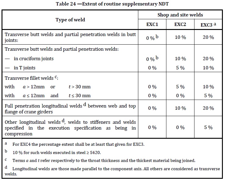
Also, if I read that text correct, it says "for CJP, ... extra prepping time for beveling the weld", implying that for a PJP weld no preparation is needed? and, for CJP, special inspection is needed, again implying that there is no NDT for PJP welds? This is confirmed a bit later that for PJP welds, special inspections are not required.

I'm not sure that is a good excerpt to quote... I'd be wary to follow this advice.
 
Re-quote below answers you question partially. For other questions, other person familiar with welding practice may answer, or you can purchase AWS D.1.1 (unfortunately an American standard). How is your code handle CIP & PJP though?

A partial joint penetration weld (PJP) is a more economical alternative for the directly welded splice. The bevel prep work is still required during fabrication, however, the weld takes less time in the field, the backing material is not needed and the special inspections are not required. When detailing the splice, the HSS shall have sufficient thickness to meet the geometric requirements of the PJP weld. The weld still develops a high amount of strength, thus the moment capacity of the splice can still be large if needed.
 
Backing bars can create areas with stress risers. This can become a problem with fatigue type (seismic) loading, causing crack initiation.

Typically full penetration welds need to be UT'd to verify that they are in fact full pen welds and don't have any issues (incomplete fusion, inclusions, etc). This is generally not a requirement for fillet welds or partial penetration welds (nor is it possible to UT test most of these welds). There are a few reasons for not requiring the special testing but perhaps the biggest reason is that the design strength for a partial pen weld is much less than a full pen weld (a partial pen weld that is 90% of the material thickness has a much smaller design strength than 90% of a full pen weld/base material).
 
Why not use four splice plates, one on each side, thick enough and long enough to develop the needed capacity, fillet welded to the lower shaft in the shop, field welded to the upper shaft. For erection; through bolts toward the top of the splice plates, one or more in each direction, and the field welded once the column is plumbed. The through bolts are for erection only, so the bolt holes in the splice plates can be oversized. The bolts can actually be threaded rod since they are not subject to loading once the splice plates are fillet welded to the upper column shaft. The threaded rod can be removed after welding or left in place. One set of opposing splice place should be a couple of inches longer to make it easier to position the upper column during erection. Just a thought.

Best regards - Al
 
Guys, I would consider your wise and intellectual advice.

Thanks in advance!!
 
How about bolted endplates? Simple to install and will give you some (but not full) flexural capacity.
 
I hope this additional discussion won't derail the original thread (too much), that is certainly not my intention...

dauwerda said:
Backing bars can create areas with stress risers. This can become a problem with fatigue type (seismic) loading, causing crack initiation.
I have no experience with seismic detailing. Is the number of cycles in seismic territorium really that high to cause such a concern? I'm talking properly welded connections with backing bars, not shoddy work that shouldn't have been executed in the first place.

retired13 said:
How is your code handle CIP & PJP though?
Design code are the eurocodes, execution code is EN 1090.
Basically, this table covers NDT. Everything is based on proper welding work with procedure qualifications and welder's performance qualifications, just sayin' this to be complete.

Table_24.jpg


All standard work (private and commercial builings, ...) falls under execution class 2 (EXC2), with large, public venues in EXC3 or when combined with "special" steels or risk for large economic conseuences by structural failure, EXC4.
 
Status
Not open for further replies.

Part and Inventory Search

Sponsor