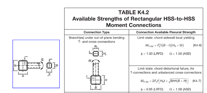
I have a simple T connection of two HSS12x8x3/8's. I am interested in making a clear hand calc, followed by a spreadsheet as I expect this connection will happen often in the future. A few parameters that are in my mind:
- this connection will be all welded.
- there will be field weld applications and shop weld applications. For the field weld a 4" long 4x4 angle "t" distance below top of steel that will slip inside the top of the beam HSS and the erector can use it to seat the beam while it is welded.
- The side walls of the beam will weld to the girder with fillet welds. There will be Flare Bevel welds at the top and bottom to negotiate the radius on the girder.
- There may be times when the beam does not match the depth of the girder, so the bottom weld will be a fillet weld and there will be an additional place to check local stresses.
- If tolerances of on site conditions are a concern, angles may be welded to the web of the girder and the beam slid between them and then welds made between the angle legs and the beam webs. This can allow the beam to be a little short and the connection will still be made. This is a little different calculation, but a simple variant if the full weld design can be mastered.
- Moments do not have to be transferred at the joint, but the frame design has considered both moment connections and pin connections and all members are fine in all conditions. The thought was to now design the connection welded all around (to keep water and debris from getting inside the tube) and make sure all cases of joint fixity are covered from a capacity standpoint.
So being unfamiliar with the nuances of these connections I have studied AISC 360-22 Section J and K. They are a bit cumbersome and I hoped for some clarity from this group. I also spent a little time on the Steel Tube Institute web page, and a little time with Blodgett.
[ol 1]
[li]Can someone clarify, is AISC 360 Section J intended to focus on simple connected joints?[/li]
[li]Is Section J focused on Wide Flange members or are the formulas valid for closed sections too? There are some notes in the text of AISC 360 that seem to indicate the formulas are valid for HSS but with some "additional requirements" in section K.[/li]
[li]Does anyone know a great resource to see worked examples of these calculations for a such a simple connection, in order to see the formulas in Section J and K in action?[/li]
[/ol]
Thank you for reading.

