Navigation
Install the app
How to install the app on iOS
Follow along with the video below to see how to install our site as a web app on your home screen.
Note: This feature may not be available in some browsers.
More options
Style variation
-
Congratulations MintJulep on being selected by the Eng-Tips community for having the most helpful posts in the forums last week. Way to Go!
You are using an out of date browser. It may not display this or other websites correctly.
You should upgrade or use an alternative browser.
You should upgrade or use an alternative browser.
HSS through bolt connection 1
- Thread starter SKKP
- Start date
- Status
- Not open for further replies.
DrZoidberWoop
Structural
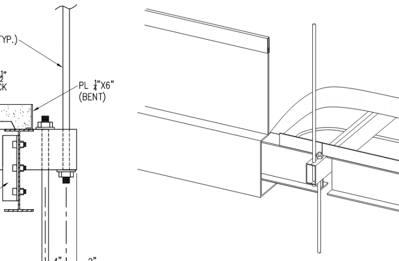
Maybe do something like this?
Joking. Couldn't resist the dark humor. See AISC 15th Eq. 9-29 & 30.

Joking. Couldn't resist the dark humor. See AISC 15th Eq. 9-29 & 30.

phamENG: While you're apparently around, THANK YOU for adding your Time Tracker excel worksheet a while back. I downloaded it and am making great use of it. I had tried various commercially available programs, but they weren't what I was looking for.
Sorry for the off-topic intrusion, but I don't know any other way to contact users on here.
As to the question in this thread:
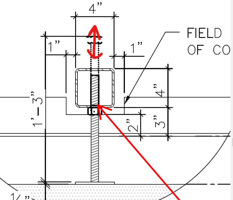
Can you add a plate to distribute the force to the vertical walls? It would be bending one way, so it'd be easy to check. Then the only limit HSS limit states would be web local yielding and web local crippling.
If you can't, then the bottom wall needs to be checked for out-of-plane bending. The AISC Manual Figure 9-5(a) and Eq. 9-30 seem to apply if you use a small c and L. I'd give that a try. If you can do a yield line analysis to verify the result, that would be good. You'll also need to check punching shear. Web local yielding and crippling still apply.
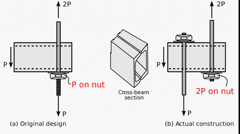
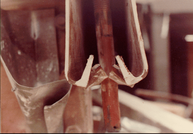
Now that we're nice and off-topic (sorry, OP) - The collapse at the Regency was due to a change proposed by the fabricator, and approved by EOR. The original design was for a continuous threaded rod with a nut at each bridge cross member. The revised design is as you see above. The failure was the top-most nut pulling through the toes of the double channels since the weight of all of the bridges below were now being supported by a single nut, as opposed to the load at each level being supported by one nut. This one always sticks in my mind when reviewing shop drawings.


JoshPlumSE
Structural
Looks a lot like the Hyatt Regency Walkway collapse detail.... Not that it can't work. You just have to make sure it calcs out properly.
-
1
- #9
People like to say the Hyatt walkway collapsed because of a construction change, like that was the whole story, but the original detail never worked anyway. No way near sufficient for design loads.
An HSS is much better than welded channels. It can work.
Check the web in bending. Either yield line, or as simple span between the flanges. Be conservative.
And make sure the holes sizes are appropriate. No oversized holes.
An HSS is much better than welded channels. It can work.
Check the web in bending. Either yield line, or as simple span between the flanges. Be conservative.
And make sure the holes sizes are appropriate. No oversized holes.
@JoshPlum
That is a photo of the actual failed connection from the Hyatt Regency. Ditto for the diagram. Both from the wiki page.
@Tomfh
I haven't done any calcs or anything, but the structure seemed to be performing as intended until this particular connection failed, which was the exact connection that was changed during CA. Although sag rods seem a bit measly for the application, even at 1.25" diameter. Were there other parts of the structure that were found to be deficient?
*edit to add this from the NIST report on the collapse:
NIST said:Based on field, laboratory, and analytical investigations, NBS concluded that:
1 . Collapse of the walkways occurred under the action of loads that were substantially less than the design loads specified by the Kansas City
Building Code.
2. The ultimate capacity of box beam-hanger rod connections can be predicted
on the basis of laboratory test results.
3. Under the action of the loads estimated to have been present on the
walkways at the time of collapse , all fourth floor box beam-hanger rod
connections were candidates for initiation of walkway collapse
.
4. Observed distortions of structural components strongly suggest that failure
of the walkway system initiated in the box beam-hanger rod connection at
location 9UE (east end of middle box beam in fourth floor walkway).
5. As constructed, the box beam-hanger rod connections, the fourth floor to
ceiling hanger rods, and the third floor walkway hanger rods did not
satisfy the design provisions of the Kansas City Building Code.
6. The change in hanger rod arrangement from a continuous rod to interrupted
rods essentially doubled the load to be transferred by the fourth floor
box beam-hanger rod connect ions
,
7. The box beam-hanger rod connection would not have satisfied the Kansas
City Building Code under the original hanger rod detail (continuous rod),
8. Under the original hanger rod arrangement (continuous rod) the box
bean-hanger rod connections as shown on the contract drawings would have
had the capacity to resist the loads estimated to have been acting at the
time of collapse
.
9. Neither the quality of workmanship nor the materials used in the walkway
system played a significant role in initiating the collapse
canwesteng
Structural
Even if the original detail did math out, how was it supposed to be erected? Have them thread a nut for 30' at each hanger? Or custom machine threaded rod to take the threads off and give it a reduced diameter between threads?
A coupler nut, could have been used to utilize the continuous rod. A separate connection above or below the HSS, could have been used. Alternatively, a weld could have easily connected rods.
Its not like its the engineers fault because they should have known the contractor would do it this way...
This collapse, and the fact the engineer claimed they didnt notice the change in the shop drawings and still lost their license, is why I'll never approve a change without a separate substitution request. I make it known at the beginning of jobs. I set a precedent.
dold said:I haven't done any calcs or anything, but the structure seemed to be performing as intended until this particular connection failed, which was the exact connection that was changed during CA. Were there other parts of the structure that were found to be deficient?
I'm not sure about the other parts of the structure, but the original design of the connections was deficient. That original deficiency PLUS the change is what caused the collapse.
From the Investigation of the Kansas City Hyatt Regency Walkways Collapse
Report said:Two factors contributed to the collapse: inadequacy of the original design for
the box beam-hanger rod connection, which was identical for all three walkways,
and a change in hanger rod arrangement during construction that essentially
doubled the load on the box beam-hanger rod connections at the fourth floor
walkway.....
...had the original hanger rod arrangement not been changed, the ultimate
capacity would have been approximately 60 percent of that expected under the
Kansas City Building Code. With this change in hanger rod arrangement, the
ultimate capacity of the walkways was so significantly reduced that, from the
day of construction, they had only minimal capacity to resist their own weight..
BridgeSmith
Structural
Re: Hyatt Regency: All they had to do was put the channels back to back, like the typical detail for that type of connection, and all would have been well.
Rod Smith, P.E., The artist formerly known as HotRod10
Rod Smith, P.E., The artist formerly known as HotRod10
- Status
- Not open for further replies.
Similar threads
- Replies
- 4
- Views
- 11K
- Replies
- 4
- Views
- 3K
- Locked
- Question
- Replies
- 8
- Views
- 5K
- Replies
- 4
- Views
- 2K
- Replies
- 17
- Views
- 4K

