Continue to Site

Eng-Tips is the largest engineering community on the Internet

Intelligent Work Forums for Engineering Professionals

  • Congratulations The Obturator on being selected by the Eng-Tips community for having the most helpful posts in the forums last week. Way to Go!

HV cable installation

Status
Not open for further replies.

bee79

Electrical
Mar 11, 2015
24
Hi All,

I'm having an issue with high voltage underground cable installation in a current project. The cable is 275kV single core AWA 1Cx1000mm2, 2 runs per phase with total lenghth up to 2.04km. The cable is laid in trefoil formation up to the concrete duct bank where cables are laid in flat formation in the PVC pipe sleeves (6nos) 1 pipe/single core cable. There will be a PEC cable installed inside each pipe sleeve for the single core cables.

The trefoil formation is 2km (cross bonding done at 3 intervals along this length)and flat formation inside the duct bank is 15m. The concrete duct bank also has rebars. I would like to know whether there will be any circulating currents in the rebars due to the magnetic field and eddy current caused by the phase conductor in the PVC pipes.If yes is there any method to calculate this current?

Also since the PEC cable is laid in parallel together with the single core cable in inside the PVC pipe, there will be some circulating currents to flow in the PEC cable as well (PEC is earthed at both end)due to the same reason as mentioned above. How to eliminate/reduce the circulating current which will flow in the PEC cable?

The basic concern is too much heat inside the busduct due to the induced circulating currents.

Please share your experience and provide suggestion to mitigate the problem.

Thank you.


Replies continue below

Recommended for you

In order to calculate the circulating current heat losses you may follow IEC 60287-1-1 section 2.3. [2.3.3].
In order to eliminate the effect of circulating current you have to assure a regular transposition of cables as per IEEE 575.
 
If there is rebar in the duct bank that encircles a single phase, then there may be circulating currents due to the magnetic flux. I don't know of any method of calculating this current or the heating that would occur. If the duct bank has not already been constructed, eliminate any rebar between the phases. Rebar encircling all three phases is OK.

You will have current induces in the single core cable shield as well as in the PEC if it is grounded at both ends. The induced shield current will be higher where the cables are laid flat.
 
Circulating currents in flat formation ductbank won't be eliminated by transposition along the trefoil route.

Two points here:

1- short flat formation for a ductbank will cause some rebars circulating currents in addition to eddy currents.

2- heating due to rebars circulating currents.

I assume that the duct is under construction.

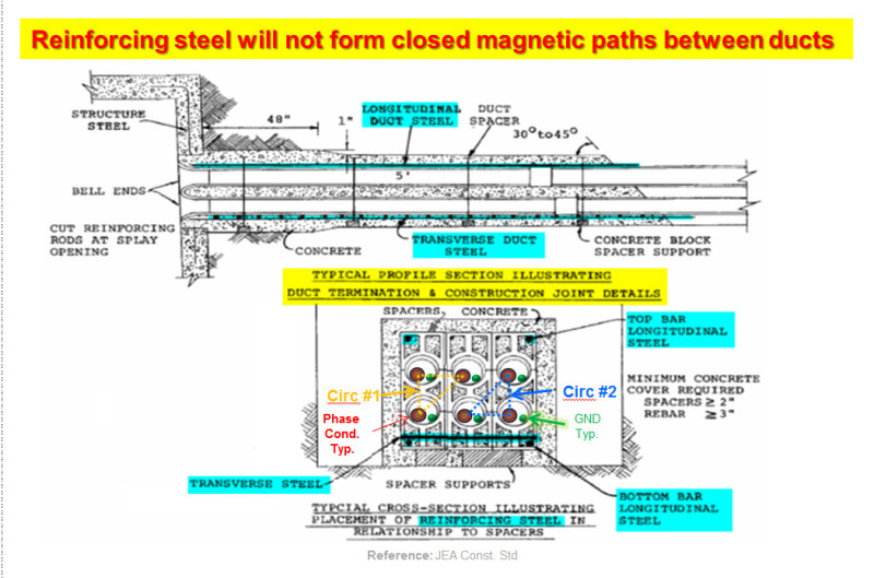
A duct with trefoil formation pipes with a ring rebars encircling them will avoid that (current summation = 0). However, if this is not possible due to design limitation, rebars should be ensured not to form a closed electromagnetic path/circuit, this will reduce the losses greatly.

Extra heating may be dissipated by increasing the overall duct dimensions and/or pvc pipes spacing.

Eddy current losses are usually very small compared with circulating currents.

If the rebars are encircling the three phases all together, heating is avoided as well.

PEC cable sheath will have some circulating current (solid bonded two points) as well due to approaching the 1C x 1000 Sq.mm cable, comparatively with the main PEC cable current and due to the spacing, I believe that the additional current (if not subtracted, depending on phase angle) will not cause major derating for PEC cable.

All these things need to be modeled with a calculation tool like CYMCAP to get a verified results.
 
Sorry, I did not remark your note these are two parallel sets of cables in the duct.
In this case you have to consider IEC 60287-1-3:
Part 1-3: Current rating equations (100 % load factor) and calculation of losses. Current sharing between parallel single-core cables and calculation of circulating current losses.
It is more complicate-I did not try this.
For reinforcing steel bar the problem is in a short-circuit case the current induced could be so high that it could disintegrate the concrete by heat expansion. No solution for this if it is happened.
In order to calculate the losses in the reinforcing bar around a single-core cable one has to
know the actual arrangement of the rebar. The losses in a plane perpendicular on the cable are only eddy current and hysteresis in the rebar. Here it has to consider that maximum magnetic flux density is about 2 Wb/m^2 due to saturation.
In a plane along the cable the losses are due to magnetic flux in the air of the loop-then the permeability[miu=miuo=4*pi()/10^7 H/m]-then a circulation current will be present.
 
Bee79, as a lesson learned, could you please let us know if there was coordination with the electrical civil engineers and if the installer was consulted during the design phase.
The first questions that should we ask is if the duct bank really need reinforced steel rebar. If the answer is yes, the next task is how to mitigate the Eddy’s and hysteresis heat losses.
If metallic reinforcement is used closed magnetic paths should be avoided. An good practice is presented in the sketch below. Beware that there is also other non-magnetic reinforced materials such as stainless steel or fiber glass.

For two circuit applications, the electrical engineer on the job should be able to advise the best transition from trefoil to flat configuration permuting the cable location of and recommend the proper shielding grounding that could minimize the losses and overvoltage impact during a short circuit event.
Duct_Bank_Reinforced_egphyx.jpg


7ANOTE4, could you please help us to understand your statement Since this is not the first time that reinforce duct bank is used, our experience in this subject is different. The cases that we see for 3 phase even with reinforced rebar in both steady state or during SC event present some challenger but no as described.
 
IEEE 142/2007 4.2.3 Concrete encased electrodes
"To ensure that high magnitude ground-fault currents do not destructively explode the concrete due to rapid drying out of the moisture in the concrete surrounding the rebar, the size of the rebars chosen for this duty is critical. The current per foot or rebar is summarized in Table 4-7."
However, if the rebar are not in direct contact-during the short-circuit to ground-with the cable conductor, I don’t think such a rebar temperature-of about 100 oC-could be reached.
 
Dear All,

Thanks for the replies. The first revision of installation drawing shows the pipe sleeves in duct bank arranged in trefoil. However contractor has changed to flat formation in the second revision. No one has review or realize about the changes since the it was correct in the first revision.

Anyway that was the history of how things went wrong and the duct bank is now finished constructed. The rebar is in between each single core cable forming closed loop.
 
Hi 7ANOTE4, thanks for the reference provided. Unfortunately I believe that the table 4-7 of the IEEE Std. 142 is associated with concrete encased electrodes where the rebar will be part of the conducting element of the concrete/steel assembly. Also the Std. 142 refers below the table to white paper by Fagan and Lee associated with concrete-encased footing electrodes (see the link below).
For duct bank application, the reinforced rebar are not intended to carry current during a fault in the way is designed for the grounding electrode. The duct bank steel rebar will only carry inductive circulating current produced by the net current of a three phase circuit.
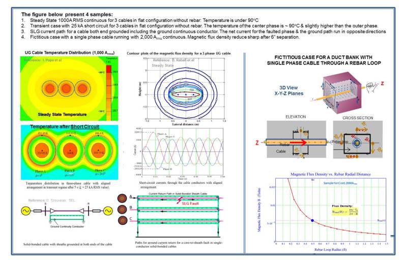
The largest net current is associated with an asymmetrical fault (Typ. SLG & LLG SC). The total current though the rebar loop is the vectorial sum of the phase conductor current and the current on the cable shield & continuous ground conductor, CGC (PEC grounded at both ends). Should be noted that fault current on the phase conductor and the ground/shield conductor’s travel in the opposite directions. Therefore, the net current is a fraction of the total fault current.
The magnetic effect on the rebar due distance to the net fault current will induce a small circulating current on the rebar and could be further reduced if there is enough separation, not closed loop, or none magnetic rebar material. In 5 cycle clearing time, the temperature does not reach critical values that compromise the duct bank integrity.
See the enclosed file with various samples that I hope helps to illustrate the steady state and transient condition during fault event.
 
Thank you cuky2000 for your information. I have already E.G.Fagan article for a long time but the second link I cannot open. However, I agree with you in the case of a duct bank the current flowing through is low. The magnetic losses [eddy current and hysteresis] are also negligible. My concern was for a parallel loop of rebar [if it could be] where the circulating current would be higher. In any case it cannot be so dangerous, I agree with you.

 
7noter4, I'm glad that we reach a consensus in this important subject for UG application.
I am attaching the image below corresponding to the second link that cannot open. I hoping the illustration below will reinforce your conclusive remarks. Thanks again for help us to clarify this issue.
Magnetic_Circuit_Losses_yo3blz.jpg
 
Due to your use of metric dimensions, it's evident that this installation is outside the USA. The codes and utilities standards and QA mechanisms would almost certainly prevent such a design or construction like that here in the US. Experienced workmen might even stop such work.

The owner of the installation will experience current imbalances and grounding conductor currents which may well lead to a shortened service life, and possible injuries and equipment damage, primarily from the heating and induced voltages. I suspect you realize this. You may also realize that such heating and imbalances are often higher in lightly loaded systems.

You should consider the costs of failure and replacement. Is this in a somewhat isolated position which would cause little secondary damage? Will replacement cause system outages?

.

(Me,,,wrong? ...aw, just fine-tuning my sarcasm!)
 

HCBFlash, please provide the rationale to support the statement quoted above.
For the described case, the heat generated on reinforces concrete duct bank do not appear to be a major problem for this application.
 
Status
Not open for further replies.

Part and Inventory Search

Sponsor