Hi
In keeping with bacon4lifes suggestion. But is becomes a long post.
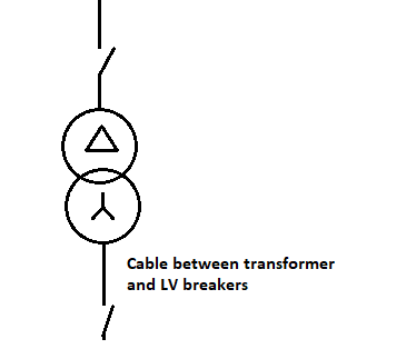
How long can the cable be after a three phase transformer
Figure 1 Cable between transformer and LV breaker
If the cable between the transformer and the LV breaker is to be protected by the HV protection, the HV protection must see the LV fault, the fault must be reflected to the HV size at a magnitude that can be seen by the HV protection.
A secondary single phase fault ends up being seen on the primary side as a phase to phase fault, with a magnitude of (TXratio*Ifault)/sqrt(3). The next two sections aim to provide insight as to why.
Sequence current explanation.
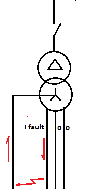
When there is a phase to neutral fault the out-fault current flows in one phase and the in fault current flows in the Neutral.
Figure 2 Single-phase fault
If the fault is in the red phase, the symmetrical component equations are:
IR = IR0 + IR1 + IR2 = Ifault
IY = IY0 + IY1 + IY2 = 0
IB = IB0 + IB1 + IB2 = 0
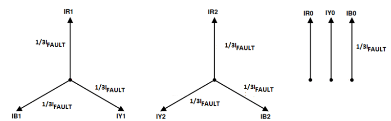
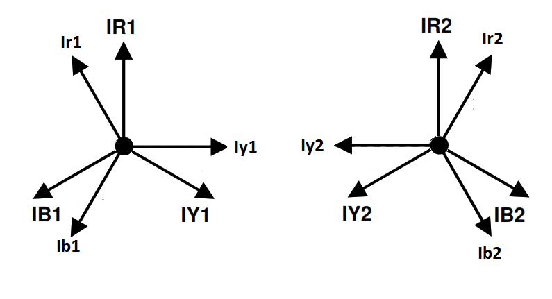
The currents can be drawn as phasers, these can be added up as vectors, that is phasers have a magnitude and direction. The solution has three sequence phasors equal in magnitude. On the primary side the symmetrical phasers offered by the fault add up as shown below.
Figure 3 Secondary side symmetrical components.
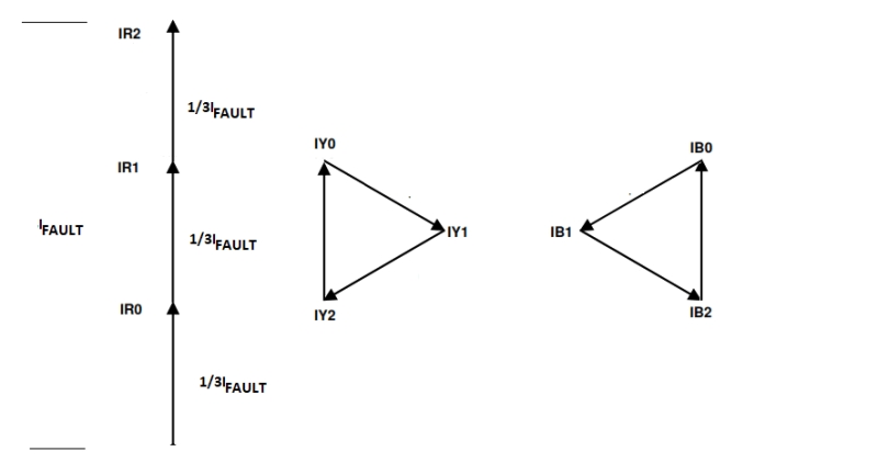
Moving the phasers around so they are head to tail.
Figure 4 The symmetrical phasers add up as required.
If the magnitude of the symmetrical component is 1/3 of the fault current the symmetrical components add up as required, that is the fault current on the red phase and zero currents in the other two phases.
To see what happens on the primary side we need to consider what happens to symmetrical components when they pass through a star delta transformer.
The zero component rotates in the delta, they heat up the delta winding but are never seen on the primary side. The positive sequence currents will be shifted 30 degrees anticlockwise as they pass through the transformer [1], the negative sequence components shift 30 degrees clockwise.
Figure 5 Positive sequence anticlockwise, negative sequence clockwise. Zero sequence gone.
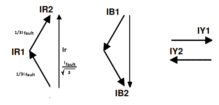
Adding up the phasors you end up with the following.
Figure 6 Summation of the primary side sequence currents.
Power argument
Symmetrical components can be used to show how the single phase fault is reflected to the HV side. Once we have established the line to neutral fault on the secondary ends up being seen as a line to line fault on the primary we can justify the magnitude using a power-in must equal power-out argument (ignoring losses):
Vout = VP-N
Vin = VP-N* ratio*sqrt(3) (it is line to line)
Vin*Iin = Vout*Iout (power in equals power out)
Let Iin =Iout/ratio*sqrt(3)
VP-N*ratio*sqrt(3) * Iout/ ratio*sqrt(3) = Vout*Iout
Cancel the ratio*sqrt(3) term and you have equality.
Single phase fault level
The zero-sequence impedance matters as the zero-sequence current must equal to the first and second sequence currents, if two phases are to be zero and one nonzero. The zero-sequence current depends on the transformers zero sequence impedance.
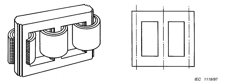
Unfortunately, the zero sequence impedance is not found on a transformer name plate. The zero sequence impedance depends on the number of legs, the winding arrangement and on which circuit you are consider ( high or low voltage). A typical three phase distribution transformer has three legs, has a star delta arrangement and our interest is the zero sequence impedance seen on the star side. The issues are discussed in IEC standard 60076-8.
Figure 7 Three limbed magnetic circuit ([2] figure 1)
For a Dyn transformer 60076-8 gives the zero sequence impedance as a1Z12, with 0.8 to 1 given as the range of a1 ([2] table 1). Setting a1= 1 makes the three-sequence impedance the same and gives us the lowest fault current, which is of interest when trying to determine if protection will pick up.
Line to Neutral impedance.
The transformers per unit impedance can be looked upon as the percentage of voltage that must be applied to get the rated line current.
Z%VLN/IL = ZLN
I= ST/(sqrt(3)*VLL)
Take ST=1MVA , VLL=415volt, VLN = 240), Z%=5% impedance
IL= 1,000,000/(sqrt(3)*415) = 1391 amps
ZS= 0.05*240/1391 = 0.0086 ohms.
For the delta case the 5% is applied to 415, so
ZD = 0.05*415/1391 =0.015
And
ZD/ZS = sqrt(3)
The single-phase cable loop impedance is also higher than the three-phase loop impedance. Three phase current goes on one phase and comes back on two. The single-phase current goes out on one and comes back on the neutral, for a system with a neutral cable size equal to the phase cable size. The three phase impedance can be multiplied by 2/sqrt(3) to give the single phase impedance. [4 table 40 notes]. That is:
Z1cable = Z3cable* 2/sqrt(3)
Where:
Z1 is the single-phase loop impedance and
Z3 is the three-phase loop impedance
When compared to three phase faults, the lower internal transformer impedance and the high cable impedance means the single phase fault current falls off faster, and this is the one to watch when working out the maximum distance a LV breaker can be from the transformer.
HV pickup above LV pickup.
We can’t go too low with the HV pickup as we want the LV breaker to trip before the HV breaker for a fault after the LV breaker. Fortunately, LV instantaneous pickups are being set lower as people start to understand the ark-flash risk. The days when Isd being set to 8 have gone.
Fault Pickup
Remembering that most faults are not bolted, relay pickup should be set to half the calculated fault current for bolted faults [3 page 3].
What reduction in cable length to see single phase fault
If we are looking at overload we only have to deal with the line to neutral overload current on the secondary changing into a line-to-line current overload on the primary, and the transformer ratio.
This is generally not an issue as attempts are made to limit out of balance loads because they produce circulating current in the transformer delta.
Our interest is line to neutral faults. Three issues have been discussed in previous sections, if we assume the 0,1 and 2 sequence impedance are the same which gives a conservative results as we are looking for minimum fault currents.
1) The line to neutral fault current is seen as a line-to-line fault current, reduce by a factor of sqrt(3).
2) The cable loop impedance, increase impedance by a factor of sqrt(3)/2.
3) The ratio of the transformers internal single phase impedance to internal three phase impedance, transformer impedance difference of sqrt(3).
If the neutral cable impedance per length is the same size as the line cable, the reduction in length needed for the primary pickup to see the same fault current is.
Sqrt(3)* sqrt(3)/2 * SQRT(3) = (sqrt(3)*3)/2
Thus, as an example, if the primary protection can see a three fault at 100 meters, the single phase fault can only be seen for:
100*2/(3*sqrt(3)) = 38 meters.