Continue to Site

Eng-Tips is the largest engineering community on the Internet

Intelligent Work Forums for Engineering Professionals

  • Congratulations MintJulep on being selected by the Eng-Tips community for having the most helpful posts in the forums last week. Way to Go!

HV Substation Ground Grid Design Based on Max Breaker De-rating Current Capability 1

Status
Not open for further replies.

cuky2000

Electrical
Aug 18, 2001
2,133
QUESTION: Should a ground grid be designed for a max. circuit breaker de-rated of 63kA for three phase or 75kA for SLG withstand capability?

BACKGROUND:
Ground grid is design is based on ground fault injected into the ground. On the other hand the breaker is limited by the three phase fault & X/R
The following data data have been used to de-rate the circuit breaker withstand short circuit capability.
A) Selected Circuit Breaker Rating:
Interrupting rating current 80 kA rms at Std X/R=17
B) System Parameters
1) Nominal system voltage: 345 kV, 60 Hz.
2) Three-phase fault................ 60 kA & X/R=50.....RESULT: SC detating estimated ~63.kA
3) Single-line-to-ground fault (SLG) 70 kA & X/R=30.....RESULT: SC detating estimated ~75.kA

 
Replies continue below

Recommended for you

In my opinion, Ith it is the required breaker rated current for the I"k prospective.
You may calculate I"k by dividing Ith by sqrt(m+n).
Let's say Ith of the breaker is 80 kA for 1 second and the prospective X/R =50.
Then ϰ=1.943; m=0.1418;
I"k max=80/sqrt(0.1418+1)=74.9 kA.

 
Typically ground grids are based on the thermal capacity of wires along with controlling touch & step potentials, whereas circuit breaker derating is based on interrupting ability. Why would the breaker derating be used for the ground grid sizing?

You certainly shouldn't design for anything smaller than the 70 kA LG fault. For clearing times on the order of 1 second, the extra heating from the DC offset could be calculated to come up with a required ground grid capacity slightly over 70 kA.
 
What is the rational for 1 second (60 cycles) clearing time? This appears very conservative since a fault longer than 15 cycles for the backup breaker to clear a ground fault is at risk of getting the system running out of control with stability problems.

Because this is the limiting factor for sizing the maximum short circuit current. There is no advantage to design a grid beyond the breaker withstand interrupting rating.
FYI, the motivation to do the extra engineering effort is to avoid unnecessary cost in the range of $1M to $3M in substation ground grid
 
Oh, the 1 second assumption was from 7anoter's comment, and it aligned with other values I have seen for 1 to 2 second clearing times for ground grid designs. I have not seen ground grid designs using such a short clearing time at HV substations, but perhaps at EHV things are done differently. Seems like the ground grid would be one of the hardest components to retrofit if the clearing time gets longer in the future.

I understand the desire to minimize the cost of the grid. I just don't understand why the same rating methodology would apply to two different physical limitations. Maybe I misunderstood what you are trying calculate? Do you have a 70 kA LG fault, and are trying to calculate the appropriate ground grid conductor size? Or do you have a breaker rated 63 kA for a 3 phase fault, and are asking if the LG fault current is ever larger than the three phase fault current?

For a 15 cycle 70 kA fault with an X/R of 30, the extra heating from a worst case DC offset would be pretty significant. If I did the integration correctly, there would be about 17 percent extra energy, equivalent to approximately 81kA for 15 cycles.
 
Bacon4life,

Thanks for your input. For this project the available SC current for 2018 is around 57 kA RMS. We are designing the grid for 70 kA to allow a reasonable margin for future growth of ~22%. This appear reasonable since the breaker de-rating for the large X/R ratio are somehow in this range for SLG to 3-phase fault withstand capability.

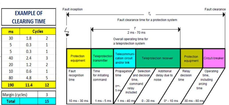
Clearing time of ~15 cycles for the worst case scenario for the backup remote breaker is achievable as shown below.
Clearing_Time_eaof9o.jpg
 
In my time we thought you should not trust the first close to equipment circuit breaker will work always. For such an expensive installation as a grounding grid you have to have, in my opinion, a backup circuit breaker within a delay of minimum 0.5 sec.
IEEE 80/2013 11.3.3 Additional conductor sizing factors recommends 1 sec.
However, 15 cycles could be good for touch potential calculation if such a touch voltage will produce in 1 second lesser shocks that are painful, but cause no permanent injury.

 
7anoter4: Thanks for your valuable inputs. I will probably follow your advise regarding the clearing time and the fusing rate of the conductor if this is a new development. Unfortunately this is a upgrade project and our task is not only to deliver a safe design but also at the minimum cost.

Any excavation to install new cable on the energized yard will be done with HydroJet and excavation by hand as follow:
. a) There is a need to reinforce the existing grid with 11,000 ft of Cu conductor : Estimated cost $1.6M
. b) There is existing 10,500 ft of #4/0 Cu conductor: If reinforced with 2nd conductor will add $1.5M


If 1 second is used for clearing time the cost will scallate as indicated above to $3.1M.

As you might see either we expend large amount of budget or perform additional engineering to meet the project goals to be safe and cost effective.

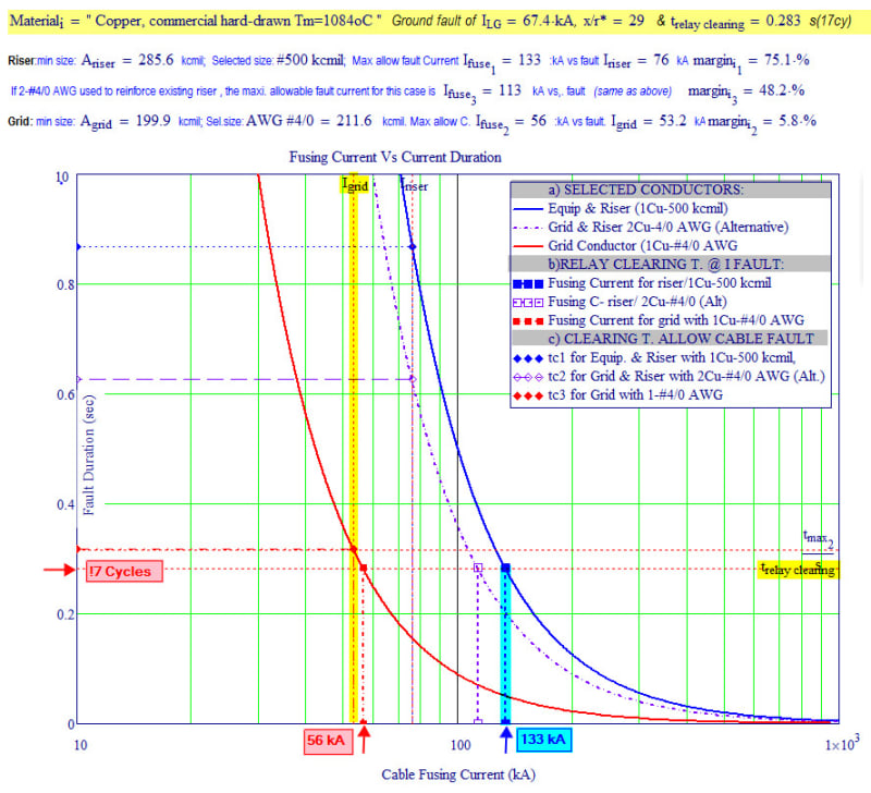
The project agree to meet the local Independent System Operator (ISO) to clear a SLG fault within 17 cycles. New protection and control system and upgrading the receiving end stations is already agree. All indicates that this clearing time of 17 Cycles is achievable for a safe duration to open a remote breakers.

Below is a preliminary assessment of the grid conductors indicating that the existing #4/0 conductor is adequate for the fault duty for the clearing time.
Cable_Fusing_Current_jlobvl.jpg
 
Hi Cuky2000,

I am with 7anoter4 on this one. The question is: if the primary protection should ever fail, what will you (or the client) do? Can the station be taken out of service while the possibly compromised grid is dug up and replaced? In most cases probabilistic analysis of this scenario supports instead spending the money up front to reinforce and be sure the grid will work.

john.
 
Hi John,

Please help us out to understand your concern (clearing time 1 sec vs. 17 cycles; Cu conductor size #4/0 vs. 500 kcmil, etc.)

I am not sure if I explained clearly that the only parameter that we can controlled is the clearing time and implement advailable mitigation techniques to have a chance to re-use the existing # 4/0 conductor:

. 1) The primary clearing time will be within 7 cycle (circuit breaker rated for 2 cycles)
. 2) Backup local for breaker 11/2 configuration (~10 cycles).
. 3) Backup remote breaker (receiving end substation) ~ 15 cycles + 2 cycles safety margin = (~17 cycles)


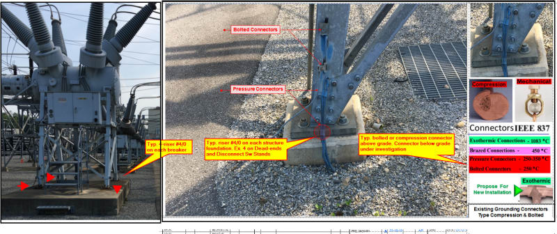
We found out that the station was built with redundant 4-#4/0 risers (pigtails) connected to different grid rather than just two risers used in regular grid design. This increase the confident level to split the fault current in a least two paths assuming that 1 or 2 existing risers fail. So the fusing current even including the decrement factor (DC offset) still appear reassonable consider re-using the existing 10,000 ft of burrying conductor ($1.5M).

NOTE:
Regarding the fault level, the available SC is 58 kA. The selected circuit breaker is actually rated for 90 kA at X/R=17 (see link below) equiped with TRV grading capacitors at both sides. Per IEEE Std. this breaker only can interrupt 65 KA at X/R=50 with available SC.
 
Can some nice people tell me what is the "risers (pigtails) " mentioned by cuky2000, I am a foreigner designer and realy don't konw that.
 
A pigtail is the vertical wire running to the equipment from the buried horizontal ground grid.
 
Cucky, can you split the difference cost wise and add more risers? This may be lot cheaper than increasing the whole grid.

Bill
--------------------
"Why not the best?"
Jimmy Carter
 
Hi Bill,

Thanks for your suggestion. This is one of a mitigation that it is propose to allow re-use the existing 4/0 conductors. We just found that the original installation used compression connector that became the limiting factor as shown in the figure below.

Grounding_Risers_-_Pigtails_levxou.jpg
 
Status
Not open for further replies.

Part and Inventory Search

Sponsor