Eng-Tips is the largest engineering community on the Internet

Intelligent Work Forums for Engineering Professionals

Hydraulic Circuit Fluid Temperature 3

Status
Not open for further replies.

nathinder

Mechanical
Nov 7, 2019
7
0
0
GB
hydraulic_circuit_uhbyaq.png


My manager has shown me this circuit its for a welding station for my revision. Its a circuit hes ran for many years thats never had problems but all of a sudden the oil tank is very hot on inspection and the system seems to be losing its ability to work. Hes asked me why and what improvements can be done? I have never done hydraulics before so just learning. Many of the findings in theory state its due to filters clogging over time or leak but the oil level in the tank is fine and theres no contamination so that makes me believe that the filters are not clogged and theres no leakage.

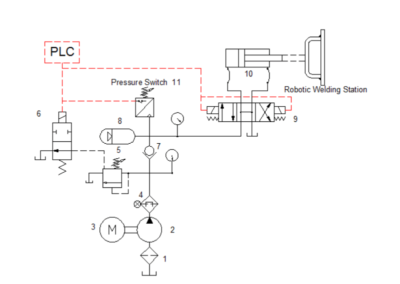
The cylinder (item 10 )operated and holds the pressure to 100 bar for 15 mins and the relief valve is set to 130 bar. Pressure switch (item 11) is set at 100 bar. when pressure is required the PLC energises item 6 and when pressure has reached 100 bar the PLC signals item 6 to unload the pump.

I am assuming that the increase of temperature is a result of an increase in pressure due to heat not being able to dissipate in the system. Is it possibly because the switch has failed to indicate the pressure has increased from 100bar and as such the PLC has not activated the 2 position directional control valve (item 6) to unload the system and due to the oil not being able to flow anywhere as a result of the non return valve (item 7) the system is just wasting oil.

The pump is a fixed displacement gear pump that is displacing at 2.5lt/min.

Item 1 is a strainer and item 4 is a pressure filter with by-pas which opens at 1 bar. Item 8 is a accumulator. Item 5 is a 2 stage pressure relieve valve.

Any thoughts on what could of caused this heat increase?
 
Replies continue below

Recommended for you

It is most likely that some component is leaking internally, allowing high pressure oil to do no external work and converting that pressure drop into heat. Check each component to see which is hot, starting at the pump. If this is a valve block, you may have to contact a hydraulics supplier or engineer to specifically inspect for worn items. One delightful option is that cavitation inside a valve can produce extra flow paths and will only be discovered with a complete teardown and careful inspection.

It is possible the filters are clogged, but I would expect them to blow out if they offered much resistance to flow.

If it is because a pressure switch has failed then the related pressure relief valve will be extremely hot.
 
Have you actually pulled the strainer and confirmed it's not clogged?

Was the fluid changed recently to a different brand/spec fluid?

Is the pump running more than normal inputting heat to the fluid?

What is Item 2/3? It appears the strainer you speak of is at a deadleg/low point. Could debris be in other parts of the line (has operating pressure increased?)
 
Most likely, valve 6 or 9 are leaking high pressure oil to drain. The leaking line should be warmer than the other other lines. But the pump could also just be worn out. This would cause the oil supply line to be warmer than the reservoir temperature.
 
I was thinking it was a result of the cavitation as you say.

I haven't pulled the strainer no. Only the oil the oil reservoir is so hot that you wasn't able to touch it and normally its at ambient temperature. The oil level was checked and its at correct level and the regular oil sample checks showed no contamination.

Fluid wasn't changed recently.

Item 2 = fixed displacement gear pump
item 3 = Fixed speed motor

if item 6/9 leaked internally would the oil reservoir still be at normal level?
 
Valve 6 will not unload the pump. It is downstream of the relief valve 5. When 6 is energized the valve blocks flow.
When valve 6 is open it can only flow oil if the relief valve opens. Then the pump is being bypassed at the relief valve pressure and generating heat.
The bypass valve should be upstream of the relief valve and connected to tank and be normally closed to only opened by the plc signal. The relief valve should only protect the system from overpressure.

Maybe the diagram is incorrect.

Ted
 
When I say cavitation - I mean it has eroded through a valve block body, not just the presence of cavitation.
Internal leakage returns to the tank. External leakage ends up on the floor.

Yes - that location of the unload valve makes no sense. If valve 6 could block the flow out of 5 then the relief valve could never open.
 
Did your manager intend for valve 6 to actuate the relief valve by blocking a port on the relief when valve 6 receives the plc signal?

Ted
 
As others have said, my first thought is that high pressure oil is being bypassed to the tank somewhere (this could also explain why "the system seems to be losing its ability to work") . Run the machine for a bit and let it get hot, then start checking valves and lines for one that is significantly hotter than the others. An IR camera is best for this, but if you don't have one an IR thermometer works well too; the back of your hand works in a pinch if you're very careful not to burn yourself. Checking the suction strainer before you do this wouldn't be a bad idea either.

As a sidenote since you're new to hydraulics: since your circuit has an accumulator (item 8), it can store hazardous energy which could cause injury when working on it if you don't take the right steps to bring the machine to a zero energy state. Since valve 9 is an open center valve, it should vent this stored pressure to tank once the machine is turned off, but you still need to verify zero energy before working on it (if valve 9 sticks, it would cause the system to hold pressure for example). If you trust both of the gauges on the circuit, checking that they read 0 should work fine.
 
Thanks guys I have understood the problem based on your replies. I think he is trying to trick me with the position of valve 6 as you suggested and purposely drawn the circuit incorrect.

I didn't notice that currently as the circuit is drawn the only way to unload the system is at pressure relief valve at item 5 since valve 6 cant unload unless the pressure relief valve 5 is open. So this indicates that the system can only unload when pressure is reached at "pressure relief valve pressure of 130 bar" which is causing the motor to be bypassed at a pressure of the pressure relief valve this in turn causes an overheat to the system. I believe as you say the circuit is drawn wrong and that valve 6 should be downstream.

It confused me cause he said it was ran fine for many years but i presume this was to trick me into believing it was internal leakage but the accumulator should account for this or for example filter blocks.


many thanks for the help i understanding.
 
Disconnect rod side hose by the directional valve #9 and check of oil is coming out when piston is in extension force. Repeat on the capped side and retraction force. If oil is coming out in large amount the Piston seal are leaking and that causes the the heat.
The accumulator is there to hold piston pressurized while pump is unloaded.
Question:
How often is pump recharging the accumulator during the 15 min cycle?

That recharging cycle time is basically the measurement of system efficiency or internal leakage.
 
It would seem that valve 6 should open the valve 5 vent to tank to make valve 5 open and unload the pump. Closing the vent would make valve 5 open at the set relief pressure, causing heat.

Ted
 
It's also not surprising that valve 6 is as shown in the schematic. Energise it to build pressure (blocking relief of valve 5, causing it to close).

What's the pressure gauge just after the pump outlet show when it is supposed to be unloaded?
 
Uh oh ...

There should be very little flow through valve 6. It is a pilot signal to valve 5, which is the main relief/bypass. The pilot valve (6) is normally-open (energise to close) so that the "default" condition of the circuit is to vent flow from the pump through valve 5. You have to energise something in order to get pressure output, and if the energisation fails for some reason then it defaults to not having pressure. Usually this is the "safe" condition - it defaults to the "safe" condition, i.e. not moving, not clamping, not pressurising.

When valve 6 is open (default, spring-loaded condition, not energised) then there is nothing aside from perhaps the spring-loading preventing valve 5 (relief) spool from shuttling open. Follow the pilot signal on the other side of it. The slightest bit of upstream pressure pushes valve 5 spool towards opening, against the spring setting, and this is what lets the main flow go through.

When valve 6 is closed (energised) pilot relief from valve 5 is blocked, which prevents valve 5 from opening, which leads to the pump producing pressure that is sent on to the rest of the system. In reality the simplified schematic for valve 5 probably doesn't show all of its internal details. In this mode of operation it probably still acts as a relief valve but at a higher pressure. Only way to know that is to track down the exact specifications for this valve from its manufacturer and go into the details of what it does internally.

In the circuit that you have here, there should be hardly any pressure at the pump outlet gauge when valve 6 is not energised. If there is, the pump is expending work to produce that pressure and it is getting lost (turning into heat) through the relief valve.

So ... check it. ALL of it.

It will probably be easiest to start at the output end of the circuit and work backwards towards the inputs. Start with that pressure gauge at the pump outlet (before check valve 7). When the clamps are moving and clamping, does it read the same as the one after check valve 7? It should (it will of course really be slightly higher by the pressure drop through check valve 7 itself, but this should be minimal). Then the gauges should go up as the accumulator fills until it reaches the pressure switch setting, at which point the pressure gauge after the check valve should stay put, and the pressure gauge before the check valve should drop to almost nil, and it should stay like that for quite a long time (since there should be no fluid demand on the system).

Is that what happens? If not, what's different?
 
Thankyou i didnt realise the use of valve 6 until i understood that it is working as a pilot signal to valve 5. I was assuming it was in the wrong place.

So i presume a combination of what you have suggested and the rest about internal leaking etc could be the possible reason why the oil reservoir is too hot to touch all of a sudden after the circuit was working fine for years.

My manager also asked if i could provide any improvements to the circuit? If the circuit is working fine for many years apart from this odd occasion of heat generation what can improve it apart from the common sense of better technological advanced equipment?


I appreciate the comments in helping me understand hydraulics.

 
If design intent and basic functionality is correct (and evidently, it has been for years) don't start trying to improve until you first find and fix what's wrong.
 
Is the piston seal leaking during the 15 minute hold portion of the cycle?
What do you mean by the system losing its ability to work? What is it doing or not doing and when?

Ted
 
Status
Not open for further replies.
Back
Top