Continue to Site

Eng-Tips is the largest engineering community on the Internet

Intelligent Work Forums for Engineering Professionals

  • Congratulations KootK on being selected by the Eng-Tips community for having the most helpful posts in the forums last week. Way to Go!

Hydraulic Cylinder Seal Configuration Back to Back Leaks

Status
Not open for further replies.

ESTinker

Mechanical
Aug 24, 2017
39
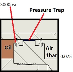
I'm trying to fix a hydraulic cylinder seal leak where the fluid has 1 entry/exit at 3,000psi and the other side open to atmosphere. There 2 U cup shaped seals (loaded with O-Ring) with a back to back configuration. I believe this creates a pressure trap and causes premature failure of the seals where hydraulic fluid leaks pass both seals. What's the best option to fix this? I was thinking about:
1. adding an O-Ring between the back to back seals
2. Replace the 2 U cup seals with O-Rings and add a U Cup seal in the middle
3. Switch both U cup seals towards the high pressure side (flip the direction on the rear seal)
4. Remove/Unload the rear O-ring on the atmosphere side to unload the seal

Seal_ilp3ph.jpg
 
Replies continue below

Recommended for you

Have you had premature seal failure or just suspect it will happen?
Is the air side at 1 bar gage or atmospheric pressure?
Any leakage will be at low pressure between the seals and will leak into the air side once it exceeds the air pressure plus seal squeeze. That low pressure fluid between the seals will not result in seal failure. If you are seeing leakage, the fluid side seal has otherwise failed.

Ted
 
It seems that this is a piston seal on a double acting cylinder and was not designed to be drip-free. If oil is expected on both sides, there would be no concern about a few drops passing. These are pressure energized seals. Having two seals in series makes it indeterminate as to what is the pressure across each seal. They are most likely to leak when there is no pressure to activate the seal, and it looks like in your application there is often no pressure on the seal.
 
Compositepro, the seals are o-ring energized to preload the seals to prevent low, or no pressure leaks.

Ted
 
I think what you are seeing is the lubricating fluid film carryover being wiped off by the seal on the air side. You could remove the preload o-ring from the air side seal to reduce the seal squeeze and reduce the effect of wiping the carryover fluid.

Ted
 
There are premature seal failures much more than a few drops. The air side is just atmosphere, basically there is a hole in the end cap of the cylinder.

I'm thinking of either removing the low pressure side o-ring or change the direction of the rear seal so both seals are pointing to the high pressure side, any recommendation on which is better or maybe a double lip seal?
 
I would look to see if the cylinder wall is damaged. Open ports invite water to accumulate and corrode the cylinder wall.
 
I'm with 3DDave. Inspect for cylinder damage or fluid side seal gland damage before blaming the seals.
You may also want to verify that the piston has no material flaws.

Ted
 
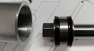
Walls look fine and cylinder is made of anodized aluminum. I should note that the leak is noticeable after about 300 cycles.
IMG_20190205_082226b_qi7p5g.jpg
 
The seal geometry does not look right. It appears the the seal can wiggle considerably as the piston moves back and forth. I think a metal spring energized cup seal would probably work better by retaining it shape better and having a better wiping geometry for preventing passing of the oil film. The sharpness of the lip in a lip seal is very important to its function.

One other factor to consider is that the surface finish metal surfaces sliding on plastic is very important. Too highly polished is often worse than too rough.

Is this cylinder your own design and construction? The reason I ask is that there are many design details in engineering that are subtle and learned through tribal experience and years of product history. Starting from scratch is like reinventing the wheel.

How are side loads on the piston rod handled. It appears that wiggling the piston rod will change the shape of your seal. That is, your seal is actually being used as a bearing for the piston.
 
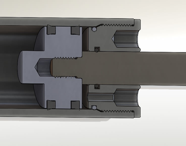
I inherited this custom cylinder design and my hydraulic experience is limited. My predecessor was more of a trial and error type. The dimensions for the seal grooves are from Parker seal design reference book. The surface finish is more on the highly polished side. The side loads are handled by an endcap threaded into the cylinder with a .0005"-.0020" of of diametrical clearance. The rod is 0.5" dia and cylinder ID is 1.25".
IMG_20190205_082226b_ii4dwn.jpg
 
The "highly polished" finish may be too smooth and allowing too much carryover.

Ted
 
Hello,

An aluminum cylinder working at 210bar: it must be verified that the cylinder has not inflated by measuring the outside diameter.

Why is leakage a problem? Because the cylinder must hold its position perfectly for hours? In this case it will be necessary to solve the problem of internal leakage.

But if it is only a problem of drops flowing outside, would not it be easier to channel this leak to the tank above the level of the fluid?

cordially
 
Estinker, an alternative would be to replace the air side seal with wiper, which really all that air side seal is in your application.

Ted
 
A few questions:

Have you removed the seals from the piston and inspected them under some magnification to look for damage? Even a simple magnifying glass can help.

Are they being damaged at some point before they are installed?

Have you removed the seals from the piston and inspected the seal groove closely? If the seals are being installed and removed using a sharp steel pick, this can easily damage the groove. A brass pick can be used, unless it's an aluminum piston, but a plastic pick or wooden popsicle stick is gentler.

Who recommended the use of those particular seals and why? Is there any documentation on why these were selected?

How hard are your seals and what is the normal operating pressure? Even with the o-ring energized seals, if you are operating at very low pressures, the shape of seal that you are using there *may* still require internal pressure to energize the seal fully if the material is very hard. Very low operating pressures with very hard seals allow leakage, as mentioned above by @Compositepro. You may be able to use the same seal in a softer material.

The need for a bearing ring may be significant.

O-rings with backup rings or X-rings with backup rings should work pretty well in this application. The seal orientation you have should not trap much pressure. If you only ever have pressure on the fluid side, then drilling a hole from the side opposite the rod into the seal groove will allow fluid to escape back into the fluid cavity while maintaining sealing. That will work with an O-ring, but probably not with the type of seals you are currently using.

As @hydtools mentions, check the material. If the piston is just an extrusion or worse - a casting, then there may be pathways directly through the material that will not hold fluid pressure. I think Chevrolet had a problem with aluminum wheel castings in the 1970's on the Corvette that had this exact problem and the tires wouldn't hold air.

Options 3 & 4 in your original post seem pretty reasonable and sound pretty close to free to try. Have you tried those yet?

Engineering is not the science behind building. It is the science behind not building.
 
I removed the seals with leaks and there does not appear to be any damage under a 10x magnification.

The seals are installed clean as they are installed with a tool to prevent any damage.

This design and seal selection was done by my predecessors who is no longer around. The seals are just standard U cup Parker seals.

I should asked if there is a better setup/way to test for seal leaks? I currently use a motor to drive a handle to pump fluid in 1" increments until the rod is fully extended (about 8 pumps) with a 300 pound load and a 15°-45° incline as the rod gets extended. This would be done about 1,000 times to check for leaks. The leaks seems to accumulate if left under load but not actually pumped over a long period of time (2 month).
 
What is the fluid?
What is the seal material and hardness?
Is the load supported?

I'm confused. You pump in fluid to extend the piston? Your illustration shows fluid retracts the piston.

Ted
 
Fluid is hydraulic oil ISO grade 46.

Seal material is Polyurethane Rubber 90A durometer with a loaded Buna-N Rubber O-Ring:
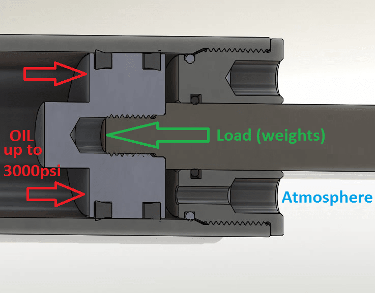
Here is some labels that should help, the fluid has the same entry and exit point with a check valve, the piston is pushed/extended when fluid is pumped into the cylinder and retracts from the force of the load when a valve opened.
pic_k0jiln.png
 
How is the cylinder ID finished? Ground, honed? If there is a spiral lay to the finish, that could allow leakage even though the apparent finish is good.

Ted
 
ESTinker said:
This would be done about 1,000 times to check for leaks. The leaks seems to accumulate if left under load but not actually pumped over a long period of time (2 month).

Can you elaborate on this setup? If the issue is that it allows a tablespoon or two of fluid to pass through over a few months under load, I don't think that that is unexpected.

You may want to turn your system upside-down so that the rod end port is facing down and fluid leakage comes out of the port as it leaks. Leave it under load and check to see if you are experiencing the same leak rate on day one as you have on day sixty.

ESTinker said:
...with a 300 pound load and a 15°-45° incline as the rod gets extended.

You need wear rings. McMaster sells those as well.

Engineering is not the science behind building. It is the science behind not building.
 
Status
Not open for further replies.

Part and Inventory Search

Sponsor