Eng-Tips is the largest engineering community on the Internet

Intelligent Work Forums for Engineering Professionals

Hydraulic Cylinder Threaded Gland Design 1

Status
Not open for further replies.

Garrett Green

Mechanical
May 18, 2022
28
0
0
US
I am designing a Hydraulic Cylinder with a threaded gland. I have experience designing hydraulic cylinders but never a threaded end. I am looking over my ASME VIII Division 1 codes to try to determine the thread engagement needed but the only thing I have found is section UG-43. Table UG-43 has a chart telling me thread engagement for NPT threads for a pipe into a plate. The issue is I am threading a cylinder into another cylinder and I am not using NPT threads.

I am assuming that threading into a cylinder is not an issue but I was curious if using different threads would allow me to use fewer threads. We will be mass producing these and the fewer turns our production needs to make the more time we save. Does anyone know a way to calculate minimum # of threads needed? my knowns are:

Cylinder max Pressure = 3000psi
Cylinder I.D. = 2in
Cylinder O.D. = 2.375in
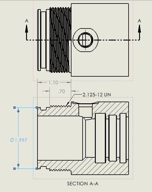
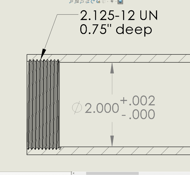
Threads (Custom machined): Major Diameter = 2.125, tpi = 12 threads

I currently have 8 threads engaged as per Table UG-43 but does anyone know if I can reduce this? If so, How do I determine how few threads I can use?

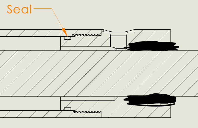
Attached is a photo of the current design.

Thank you,
 
 https://files.engineering.com/getfile.aspx?folder=9e0f700c-93d3-40e3-9462-931028046031&file=Capture.PNG
Replies continue below

Recommended for you

After posting I realized there is a "Fluid Power Engineering" Forum and I probably should have posted there. I do not know how to move this thread so I am hoping someone here will be generous enough to help me out!

Thank you
 
I have designed something under VIII-1 not so long ago. Also non NPT, non standards code stuff. If you have a bit more sketch details I can see if I can help.

Huub
- You never get what you expect, you only get what you inspect.
 
I will have this drawn with all details soon, but is there something specific you need to know? The material of the tube (outer threads) is st52.3 dom tube, yield strength=52,000psi. The Gland (internal threads) is C12L14 yield strength=75,000psi. I feel like materials with size of material, type of thread, and forces should be enough. I will share my drawing when it is complete with dimensions but please let me know what you are looking to see.

Thank you,
 
Perhaps some more details on the sketch, to check if it met my situation. What I was struggling with was that there was no (UG-)code section really that catched my situation, so I had to kinda build something that was derived from App 2 stuff.
You may look at this topic I made on some issues I ran into. Let me know if that helps.

Huub
- You never get what you expect, you only get what you inspect.
 
We used to build pressure equipment with 52.3 housing and 4130 end fittings (normalized, about 63ksi yield).
We used two different threads depending on the actual pressure.
For typical applications we used a std straight "V" thread.
And we used long engagements, >16 threads (mostly for alignment reasons).
For high pressure applications we went to modified square thread profile (we paid a license fee and used something like a VAM).

= = = = = = = = = = = = = = = = = = = =
P.E. Metallurgy, consulting work welcomed
 
Capture1_sbxqn9.png

Capture2_aqn9um.png

Capture3_ptob0a.png


This should give you all information involved with how these attach. I didn't want to show all dimensions on these parts because they are parts that we are designing to build in house and sell. I think App 2 and App Y do not apply because they are about the force the bolts need apply to seal properly (if I am reading them correctly). As you can see on these images, the seal is accomplished by the tolerance fit between the two parts. The only factor I need to consider is that my threads will hold up when the cylinder is fully pressurized. The force at full pressure will be 3000psi * [pi*1^2]in^2 = 9425lbf.
 
That looks a lot like what we were doing.
Into a honed bore you don't need a special land for the o-ring.
But the transition from the ID to the first thread is super critical so that it is smooth.
Adn being able to install these without the lead lip of the head damaging the ID surface where your o-ring will seal is a balancing act.

= = = = = = = = = = = = = = = = = = = =
P.E. Metallurgy, consulting work welcomed
 
EdStainless,

Thank you for the heads up in regards to the transition from the threads to the ID. I will make sure that is smooth.

To help damage to the ID sealing surface, would changing the chamfer to a large radius help prevent any scratches?

Also when the threads start, the end of the lead lip will still be over the threads, and by the time it reaches the sealing surface of the ID the threads along with the seal should be aligning the part to not scratch the tube wall. However, my big concern with this is spinning that seal over the threads and it cutting into the seal. Did you ever run into that issue?

Thank you
 
We had the tolerances on the o-ring, the groove, the threads and such all skewed slightly so that regardless of how they stacked up we had enough clearance.
We rarely nicked an o-ring.
We did very slightly take the points off of the thread profile.

= = = = = = = = = = = = = = = = = = = =
P.E. Metallurgy, consulting work welcomed
 
I would use the Handbook of bolts and bolted joints.

D = bolt OD
n = threads per inch
SInt = internal thread material allowable stress
SExt = external thread material allowable stress
A = pressurized area
P = pressure in cylinder
dp = pressurized diameter
Le = actual length of thread engagement

A [in2] = π*dp²/4
T [lb] = P*A ~ tensile load due to internal pressure0

Tensile Stress Area: Handbook of bolts and bolted joints, pg. 135
As = π/4*(D-(0.9743/n))[sup]2[/sup]

Useful Thread Length: Handbook of bolts and bolted joints, pgs 136-138
Case 9.4 (LE1): nut stronger than bolt, Case 9.5 (LE2): bolt stronger than nut, Case 9.6 (LE3): equal nut and bolt strength
LE1 [in] = (2*As)/((π*n*D1max)*((1/(2*n)+0.57735*(d2min-D1max))))
LE2 [in] = (SExt*2*As)/((SInt*π*n*dmin)*((1/(2*n)+0.57735*(dmin-D2max))))
LE3 [in] = (4*As)/(π*D2bsc)
LE [in] = IF(SInt>SExt,LE1,IF(SExt>SInt,LE2,IF(SInt=SExt,LE3)))

Thread Shear Area: Handbook of bolts and bolted joints, pgs 136-138
Case 9.4 (AS1): nut stronger than bolt, Case 9.5 (AS2): bolt stronger than nut, Case 9.6 (AS3): equal nut and bolt strength
AS1 [sq.in] = (π*n*LE1*D1max)*(1/(2*n)+0.57735*(d2min-D1max))
AS2 [sq.in] = (π*n*LE2*dmin)*(1/(2*n)+0.57735*(dmin-D2max))
AS3 [sq.in] = (π*D2bsc)*(LE3/2)
AS [sq.in] = IF(SInt>SExt,AS1,IF(SExt>SInt,AS2,IF(SInt=SExt,AS3)))

Maximum Tension Load: reduces the joint strenght if the actual thread engagement is less than the useful thread length
StrRatio = IF(Le<LE,Le/LE,1)
FInt [lbs] = (SInt*0.8)*AS*StrRatio
CheckFInt = FInt>T
FExt [lbs] = (SExt*0.8)*AS*StrRatio
CheckFExt = FExt>T


Thank you all for your input!

Cobra, That is exactly what I was looking for. Thank you so much! I will work through this to determine what is needed.
 
Status
Not open for further replies.
Back
Top