Continue to Site

Eng-Tips is the largest engineering community on the Internet

Intelligent Work Forums for Engineering Professionals

  • Congratulations GregLocock on being selected by the Eng-Tips community for having the most helpful posts in the forums last week. Way to Go!

Hydraulic symbols 7

Status
Not open for further replies.

dbag123

Mechanical
Oct 22, 2019
1
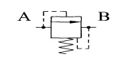
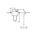
What are these hydraulic symbols?
Thanks
12_pxs1wf.png
23_rlsdhv.png
 
Replies continue below

Recommended for you

They look like some kind of pressure control valve, the symbols at least look like a combination of a pressure relief and a pressure reducing valve. I'm not sure exactly what they are however. Hopefully that gives you a starting point for some research (or someone more knowledgeable comes along). Here's some links that you might find useful:
How To Interpret Pressure Valves
Pressure Relief and Regulating Valves
 
Hello everybody:

That symbol seems more like a Sequence Valve.

El que no puede andar, se sienta.
 
A pilot-operated to open check valve. Downstream pressure holds it closed. Upstream pressure opens it. The one on the left has a drain to tank. The one on the right has both a spring and dowstream pilot to close it.

Ted
 
hello

The secound one looks IS a non adjustable direct acting relief valve. The sun site mentioned above is one of the best for symbols and descriptions.

The first one would take some checking. Could be a type of pressure reducing, but it may be missing the arrow

See below for more symbols then you may care to know


No guessing here on the second symbol, it is what it is.

Note: that a Pilot operated valve Can use the process pressure from the #2 line, which may not be considered external. See the sun link for various examples.
 
First of all, questions like this can never be answered properly when the valves are cut out of context.
This is also a typical "student question" from someone trying to "learn" and a lot of answers are coming from people are "guessing" which of course creates a debate.
Any valve out of context can be analyzed differently because we all have different experiences. from symbol applications.

Another problem is that there is no exact 100% commonly used standard of symbol drawings and neither there is a 100% commonly used standard of interpreting and putting symbols into system context.

Neither one of these two valves can be considered "pilot operated" since there is no external pressure signal line involved in the symbols.

The valve to the left needs more "context" and the origin of the source. As drawn I have never seen it before. The valve to the right is as I interpret it drawn as a pressure relief valve. The control line from spring side to the B port is a drain function.


Pressure relief valves are NORMALLY CLOSED and drain to the tank.
Pressure reducing valves are NORMALLY OPEN and supply a downstream part of the system with lower and reduced pressure. As an example, the pilot lever control system in an excavator.
pressure_relief_and_pressure_reducing_valves_qo3l47.jpg
 
hello every one

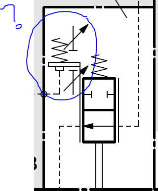
what this hydraulic symbol means?I confused about it,please help me.
I highlighted that.

Capture_itdblv.png
 
mostafa2932
What's the rest of the "context" around the valve?
 
Hello
The symbol on the right is a two way valve. Normally open. Solenoid operated to Close the flow.
The other symbols do not look like they belong there, maybe a drafting error.
 
Looks like it could be part of a pump control (possibly torque limiter).

The directional spool is mechanically operated inside a sleeve which is pilot pressure positioned between two adjustable maximum stops.

Agree that the rest of the circuitry is required to see the context.
 
Status
Not open for further replies.

Part and Inventory Search

Sponsor