Eng-Tips is the largest engineering community on the Internet

Intelligent Work Forums for Engineering Professionals

Hydrophore filling pumps running of curve 1

Status
Not open for further replies.

samski

Marine/Ocean
May 9, 2024
6
0
0
NL
Good morning,

As a student Marine Engineer and Electro Technical Officer I have to complete a thesis. This is a report focused on answering a research question. The engineering team onboard has suggested that I research the feasibility of installing frequency drives on the hydrophore skid.

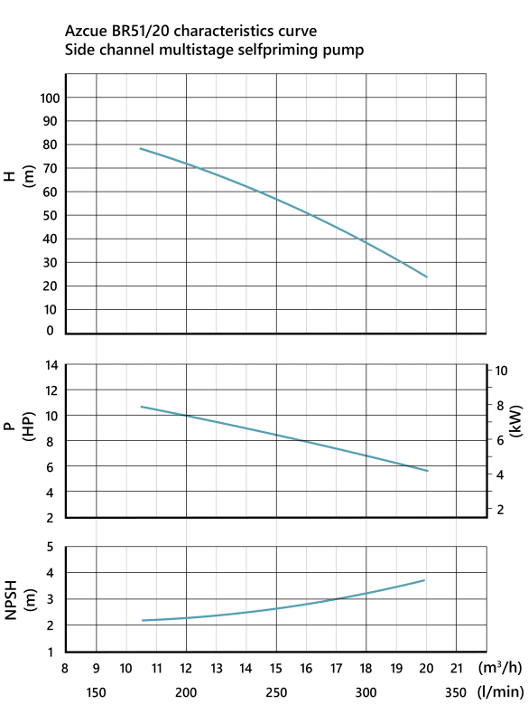
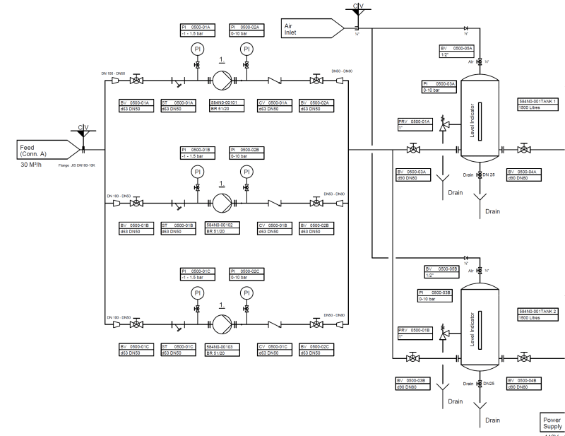
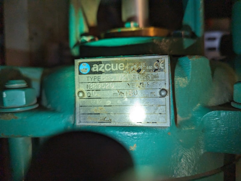
The current hydrophore is a setup with two 1500L buffer tanks under 7.5 bar pressure, with three multistage self-priming pumps, capable of a total of 30m3/h. These pumps are used (not at the same time, alternating to keep the running hours equal) to fill the pressure vessel.

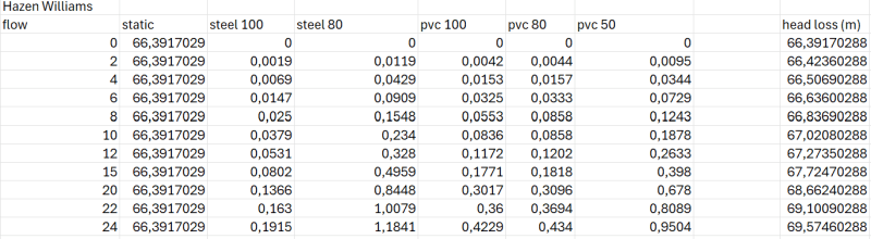
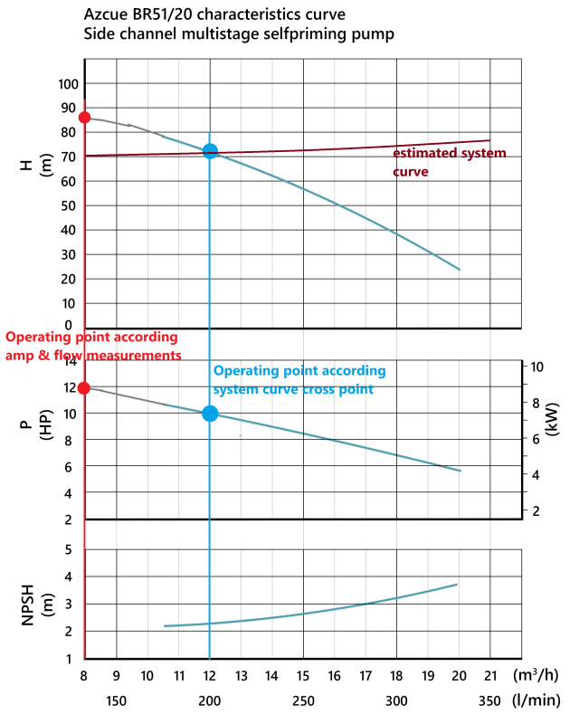
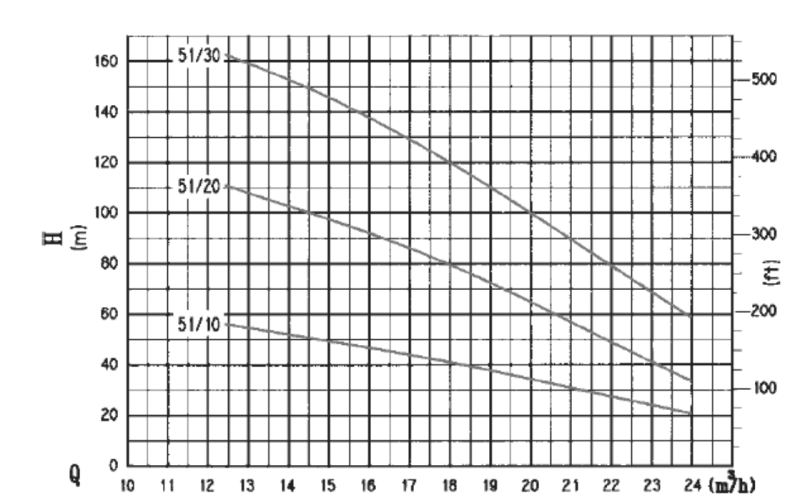
I have taken the pump curve from the datasheet of the pump and plotted this in Excel, together with the calculated (according the affinity laws) pump curves with lower speed. I have also calculated the system curve. The static head is high, as the pumps turn on at 6.5 bar and stops at 7.5 bar. The friction head is quite low because it is a small pumping system (around 20m of pipe with various fittings etc, pump suction height equal to the tank suction height and the discharge is also on the same level), resulting in a flat system curve.

pumpcurve1_uz9vmo.png


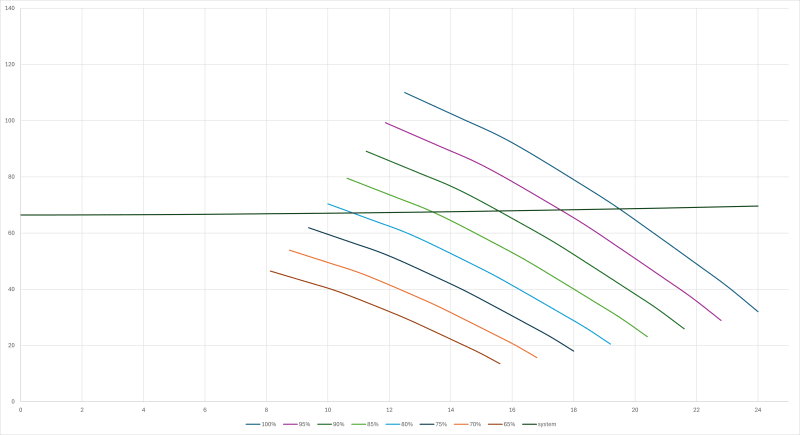
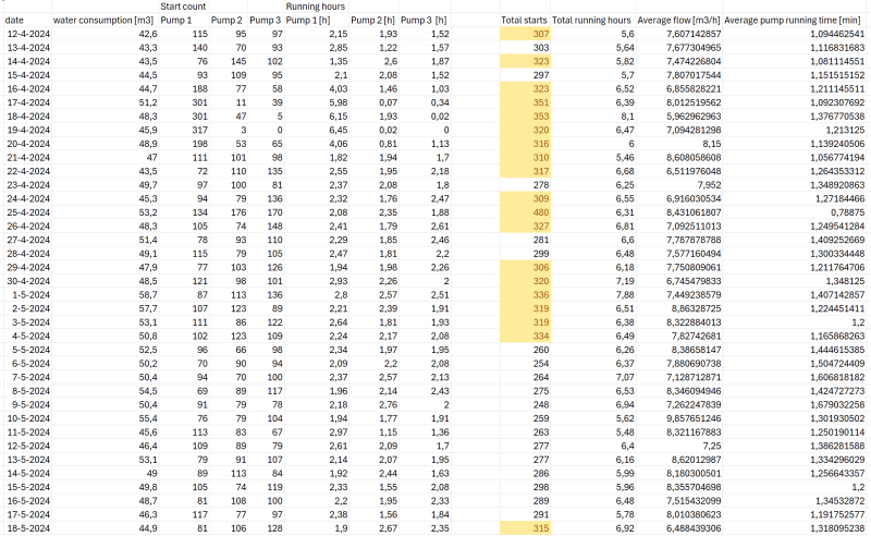
But now I measured and calculated the average flow of the pump around 11 m3/h during a filling cycle, which is way of the crossing point of the system curve and 100% operating curve.
I hope you could explain me why this is.


Kind regards,
Sam
 
Replies continue below

Recommended for you

What is the suction pressure doing? Pump flow may be limited by the suction line size.
Is the suction pressure higher than NPSHR at all times? Perhaps it is too low, thereby limiting flow by cavitation.

--Einstein gave the same test to students every year. When asked why he would do something like that, "Because the answers had changed."
 
Please post the pump curve.

You haven't included any head required on the inlet side, but as these are self priming, this implies there is a suction lift, i.e. negative head?

Also the 20m of pipe and no doubt other valves etc equates to some friction loss, not zero. What is it? you don't seem to have shown ANY frictional losses

From your data, the implied frictional losses seem to be quite high - about 30m at 100% speed but depends on what is in the line from the pump to the tank. Have you got a P&ID or schematic?
Is there a pressure or flow regulating valve anywhere?

Normally high static head systems perform badly in VFD usage as the variability in flow is only about 20% before you run out of head to actually get any flow and the difference between one percent in speed can be quite big in terms of flow.

Why do you want to vary flow and by how much?
I would normally just use a control valve - much easier and cheaper.
Remember the VFD eats power itself - about 8-10% of pump power and packs out the heat inside your control room or electrical room.


Remember - More details = better answers
Also: If you get a response it's polite to respond to it.
 
Hi all,

Thanks for the answers.
I observed the pump during a cycle of filling, and the suction pressure without the pump running is 0.5 bar, and when it starts 0.1 bar. This goes up to 0.15 bar close to the end of the running.
The discharge pressure of the pump is ofcourse 0 without the pump running (check valve), and when it starts 6.4 bars which increases as the pressure in the vessel starts rising.
Average amperage on the electromotor connected to the pump during running of the pump was 12~13 amps.

This is the original pump curve:
pompcurve1_zzwjta.png


For the frictional losses, I have measured and collected all the fittings that are in the system, and used this site/calculator: I took the Head friction loss from the Hazen Williams Equation as this was the most conservative. This head loss is the plotted system curve in my original post.
Schermafbeelding_2024-05-11_024803_jkvapx.png


PI&D drawing of the system:
piddrawing_qp1ilz.png


If it would be possible, I would want to keep the pumps, but with a frequency drive that can keep up with the live consumption/pressure drop in the vessel and that stops when there is no flow. This would prevent high pressure shocks in the PVC system which often causes pinholes and leaks, and the very often starting and stopping of the pumps (around 300 times a day). These pumps might not be suitable for this solution, but no is also an answer on the research question, where I can offer alternatives.
A bit similar like this, which has been implented on other vessels from the fleet:

Kind regards,
Sam
 
What liquid?
Water?
Vapor content?
Temperature?

What is the rated flow capacity and power of the pump?

Are the pressures you mention gage pressure, or absolute pressures?

How is the pump being controlled now? Is it VFD running at 80% speed?

VFDs are useless when discharge pressure must be maintained within a tight margin. You can only produce a very small range of flow rates. A constant speed pump is perfect for doing that.

Your flat system curve is because your vessel has a constant operating pressure of 6-7 bars. Little to do with elevation or flow rate.

The explanation is that your pump is running at 80% Speed. That gives you a flow rate of 11m3/h and a pressure of 6.7 bars. That's what you need. Thats what the pump does when running at 80% speed.
You got it. It can be easily done with constant speed pump, so your VFD is not required, therefore a waste of money and maintenance dollars when compared to a control valve option.

I would think that pipe pinholes are not caused by waterhammer.
I would thing a constant speed pump would have a shut off switch for when pressure is not needed. That is the ONLY control needed for a constant pressure, constant speed pump


--Einstein gave the same test to students every year. When asked why he would do something like that, "Because the answers had changed."
 
I'm with mr 44 here.

The error seem to be in your excel sheet or as mr 44 says, your pump is operating at 80% speed.

Is this a motor designed for 60 htz (3600 rpm) running at 50 htz? (3000 rpm?)

VFD simply won't work. what you need is a control valve and a flow meter.

CV based on liquid level or what ever you are using to control.

Actually what are you controlling on? The P&ID doesn't seem to have any instruments(!) So how does it turn on and off.

Is the air pressure constant?
How does this system work now and how do you want it to work.

Describe that a lot better and we might get somewhere....

Remember - More details = better answers
Also: If you get a response it's polite to respond to it.
 
With 300 starts and stops a day, I would think that you might have a high pressure shut off rigged to the pump, which pressures the tanks too fast and shuts off very quickly.

Trying to slow down the pressuring of the tank by using a vfd running at lower than 80% will slow down the pressure rise, but will also NEVER reach your your 6.7 bars. You need to run at 85 to 90% to reach 7bar. It will be a lot cheaper to do with constant speed and control valve.

Another solution for future designs might be to increase the volume of the tanks, or reduce the flow rate of the pump, so it takes more time to fill them. As it is now, the Pump may be too big And/or the tanks too small, so they pressure up quickly, then run out of pressure too fast when the pump is off.

--Einstein gave the same test to students every year. When asked why he would do something like that, "Because the answers had changed."
 
Good morning,

Thanks for all your thinking with me.
This hydrophore system is used for the potable water supply on the vessel & the above mentioned pressures are gauge pressures.
The water is around 15 ~ 18 degrees celcius and there is an average water consumption of about 50 m3 a day.

The electric motor coupled to the pump is powered by the 440V 60Hz net, and has a nominal speed of 1760 rpm at 28.7 amps.
The pump is currently controlled by a start stop system depending on the pressure in the vessel. A Danfoss pressure switch starts the pump when the pressure drops below 6.2 bars, and shuts off the pump when it reaches 7.5 bars.
I have attached a datasheet of the pump that is used. The specific type is the BR51/20.

The air in the vessel is constant. The pressure vessel is filled with a specific amount of air, which does not change. This is only filled when the pressure has severely dropped or when maintenance on the vessel has been done. Currently, the two vessels are both in use in parallel, meaning that 1 pump fills both vessels and they are both emptied by water consumption on board.
There is a big difference visible when running on one or two vessels. When one vessel is in use, the pumps start roughly 500 times a day with an average running time of 45 seconds. When two vessels are in use, the pumps start around 300 times a day with an average running time of 90 seconds.

The thing I want to know is why my system curve is that far of the current operating point of the pump. As I've mentioned in my first post, I measured the flow of the pump at around 11 m3/h during a filling cycle while the cross point of my calculated system curve and the pump curve this should be around 19 m3/h.


Kind regards,

Sam
 
 https://files.engineering.com/getfile.aspx?folder=21ca4f82-eb7d-4048-9738-63d414b20bf6&file=BR_Datasheet_compressed.pdf
There may be some errors in the pressure drop calcs, assuming your fill rate of 11m3/hr is correct.
It sure looks like you tanks are too small for the average consumption downstream of the tanks.
Another alternate to VFD would be to install a self operated backpressure recycle valve on each pump discharge that kicks water back to the source tank upstream of the pumps. Set this recycle valve to some 7.5barg. Design case flowrate for this backpressure valve would be min flow for this pump at 100% speed. No need for pressure switch to stop / start the pump. Pump will then run continuously. Pump and motor wont last long at 300-500 stops/day - bearings will fail.
What are these "pinhole leaks"? Are these bladder tanks?
 
If your pumps are constant speed they should be pumping a flow of 20m3/h, when they are operating, but they do not operate 100% of the time. You are apparently measuring average flow rate over a long time period, 24 hours? of about 264 m3 per day. So 264m3/24h = 11m3/h and actual pump operating time in that 24h is only 11/20 = 55% of the time. 55% of 24h = 13.2h

The on/off switch will easily pay for itself.

--Einstein gave the same test to students every year. When asked why he would do something like that, "Because the answers had changed."
 
OK.

Trying to make sense of what you've given us.

The pump curve you posted on 11 May 01.10 is for the 50Htz, 1500 rpm machine. You tell us you have 440V 60 htz, presumably 3 phase. At you quoted amps of 28.7, this is a power into the motor of about 18.5kW. Shaft power is probably about 17kW. The size 51/20 curve show this to be about 10 or 11 m3/ hr and off the left hand side of the curve, so not really a good idea, but equates to your measured flow.

The discrepancy now is that this would be at a discharge pressure of about 12 bar. So somewhere between the pump and the tank there is an additional pressure drop. You need to physically check the entire pipe run to see if someone has inserted a control valve OR some one in trying to reduce the number of starts has throttled one of the isolation valves to slow everything down. Ask the operators what they've done, but they might lie to you so go check yourself.

The root cause though is the small pressure difference between on and off. In your 1500l vessel I would guess the tank level is never more than about 60% full at 7.5bar and hence it probably only takes 100 l of water to drop to 6.5. Why don't you go look at what is happening with the tank between on and off. At 300 starts a day you won't have to wait for long....

But this level of starts is insane. You either need to allow the pressure to drop to something like 2.5 bar then back up to 7.5, add more tanks or add an Automatic Recirculation Valve (ARV) - look them up - which allows the pump to run continuously at low flow unless the flow is needed.

A VFD for this situation won't work.

But first find out why the pump discharge pressure (what does the guage say??) is being lost between the pump and the tank.

OR your 11m3/ hr is wrong, but the amps are too high for 20m3/ hr. At 20m3/ hr it should be about 15 A

OR fit different sized pumps and stagger the start pressure. So initially start say a 2m3/hr pump, then if the pressure falls, start a 5m3/ hr pump then a 10. Or something like that depending on your max demand. If you don't have data to tell you demand over the day FIND IT. Only then can you make proper design decisions. Poor data, poor decisions.

E.g. you say the average daily flow is 50m3. So having a set of pumps able to do 30m3 per HOUR seems very wrong.

Remember - More details = better answers
Also: If you get a response it's polite to respond to it.
 
Concur with the opinion that in thins case VFD control for constant pressure discharge does not have the control turn down range needed.

Your pump cycles are however way too short, which indicates to me not enough storage in your tanks. Storage can be increased by allowing the pressure in the tanks a wider range. Water users with tight pressure requirements can be provided with spring loaded pressure regulators. Most users will be able to tolerate moderately large pressure swings.
 
Hello all,

It has been some time, have been busy with normal work. I've had some time to do some more measurements on the system.
Took a clamp meter to measure the current of the electromotor, measuring around 15 amps.

I also timed a pump run (exactly 1 minute) and measured the height the vessels increased in volume, making it possible to calculate the pump flow (one minute, 9 cm increase -> vessel inner diameter of 98.8 cm gives a volume of 0.07 m3 for each vessel -> 0.14 m3 in one minute, gives 8.4 m3/h).

Also keeping track of the running hours and starts of the pump, see below screenshot.
Marked in yellow are the values above average. 25-4-2024 has a peak amount of starts, this was due to maintenance on one of the hydrophore vessels, making the system run on 1 vessel.
collecteddata_a0yjdm.png


Then I had a quick look on the pump info plate and got very confused.

PXL_20240519_025450908_whktjz.jpg

(Picture is rotated 90 degrees clockwise)

This plate mentions a Q of 10 m3/h with an 80 meters head, while all documents on board and found online mention an 18 m3/h at 80 meters head? Type BR51/20RR, running at 60 Hz.
[URL unfurl="true"]https://www.castlepumps.com/images/uploads/datasheets/BR_Datasheet_compressed.pdf[/url]

This could explain the offset of my pump curve and system curve, because I am now doubting the pump curve that is used in all documents.

Would love to hear your opinion on this.


Kind regards,
Sam
 
Nameplate with equal measured values evidence cannot be denied.
The answer was hiding in plain sight.
Mystery solved.

--Einstein gave the same test to students every year. When asked why he would do something like that, "Because the answers had changed."
 
Yes, but name plate doesn't state rpm...

If the pump has been combined with 60Htz supply and motor it will do more. You need to double check the frequency of the supply.

Also you need to include the outflow which might be occurring at the same time.

45m3 over say a 16 hour average is 2.5m3/hr so you pump is probably doing much closer to your 10m3/hr.

But you key issue remains- far to many starts so you either need to adjust the start stop pressure range or have more storage or run the pumps continuously but with a low flow bypass or install a smaller pump to operate unless you really need more flow than your average flow of about 2.5 m3/hr. IMHO.

Remember - More details = better answers
Also: If you get a response it's polite to respond to it.
 
Also the power at 15 A 440V is about 9 to 10kW shaft power.

That equates to your 50 htz machine at about 9 to 10m3/hr.

Everything is telling me that pump is working at 50Htz somehow. Maybe there is a frequency convertor on that set of pumps??

Remember - More details = better answers
Also: If you get a response it's polite to respond to it.
 
Good afternoon,

So I am back on this research project. Answering LittleInch his questions:
I am 100% certain the pump is running 60Hz as the whole ships grid is 60 and with the current measurements I also measured 60 Hz. The curve I attached in my first post is also the 60 Hz (1750 rpm) curve

I redid some drawings and calculations and results are below.

With the measured amperage and flow at an average 7 bars, the working point of the pump is left of the curve at 8 m3/h with 85 m head and 9 kW (~14A). It is inline with the curve, but it is just very low and out of the working limits of the pump.

With the calculated system curve and estimated pump curve in excel, I get a working point of about 12 m3/h at an average of 7 bars. This is on curve, but definitely not what the pump is operating at. I checked the whole piping system etc, but there is no extra throttling or other pressure increasing parts that have not been included in the system curve calculations.

See drawing below. I extended the power and head lines a bit with grey color for estimations.

pompcurve2_-_kopie_snfgez.png


How is it possible that the pump is operating that low and of the curve? What are the effects on the pump?

Kind regards,
Sam
 
Only thing we haven't talked about for some reason is what is the actual diameter of the impellor?

Or these are multi stage pumps? ( the second number appears to be the number of stages) So maybe you've actually only got 15 stages and 5 dummy stages? Or just 15 stages. Have you counted them?

Have you tried the original vendor and asked them the details suing the pump serial number? The name plate tells you something is not standard here.

It does say in their blurb that each pump is "manufactured to order". SO the curves are really just generic and they mess about with the pumps to suit what each party wants. Someone clearly didn't want to have more than 8 bar a the design flow so that's what they gave you.

Oh and I don't understand your curves above. So e.g. at 12m3/hr with 20 stages, the pump is putting out about 110m, not the 70 you're showing in the curve.

If your curve is the one that came with the pump then it proves my point - the pump you have is different to the max 20 stage pump.

This is the 51/20 @ 1760 rpm from the vendor.

Screenshot_2024-06-12_170003_tspicz.png


Remember - More details = better answers
Also: If you get a response it's polite to respond to it.
 
If what you mean is what happens leading to the left hand of the curve, its greenbelt not good, but can work for a long time. You are generally quite inefficient and the pump tends to have more recirculation within each impellor leading to excess wear.

However the vendor gave it to you at the rated flow of 10m3/hr so they must be happy with it.

Remember - More details = better answers
Also: If you get a response it's polite to respond to it.
 
Status
Not open for further replies.
Back
Top