binsky3333
Computer
Hi everyone!
I have a computer science background (this is my first big personal ME project)... so don't be too harsh on me heh.![[tongue]](/data/assets/smilies/tongue.gif "[tongue] [tongue]")
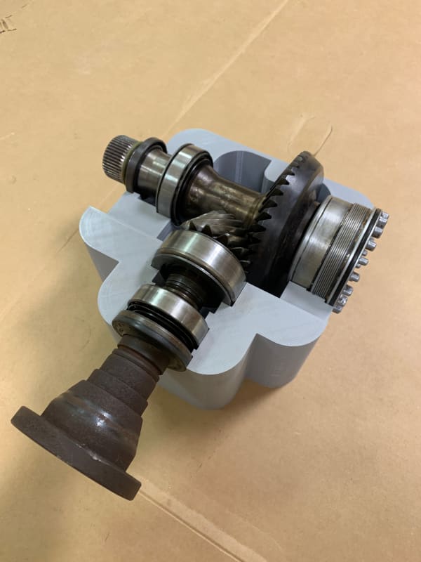
I have a hypoid spiral bevel gear set that I am designing a new case for. The original case is very cheap cast aluminum that breaks very easily. This piece is a transfer case thats send power from the front of the car to the rear wheels.
I am working on calculating the gear tooth forces and then calculating the forces on the shafts. I have already prototyped the case for testing gear fitment but want to calculate the forces and then do some FEA on my prototypes before I go any further.
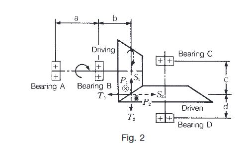
Here is a picture to get an idea of what I am talking about. The torque is input through ring gear (yes you read that correct) and output through the pinon.
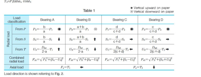
I have been using the following website to calculate the gear teeth forces :
Specifically this table... from my understanding of bevel gears the tangential force is calculated the same way for all types and only the axial and radial change based upon whether its straight, spiral, zerol, etc.
Ignore the values in this table, they are just example values.
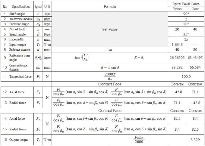
I did some calculations by hand in excel, but found out the KHK Gears website had an online calculator using the exact table above. I ran a calculation with ~3300nm of input torque on the ring gear (or 1000nm output on the pinon, 3.31 ratio). I came up with the following:

Now that I knew my tangential, radial and axial gear tooth forces I could calculate the actual forces on the bearings. To do that I use the following two websites:
(I used page 3 to calculate the tangential, radial and axial and then combined)
(This I used to just get an idea on the tangential forces on the bearings but also has good info on calculating combined)
This is where I started second guessing myself. The gear tooth forces seemed pretty realistic to me and I found the same math on a lot of different websites indicating its pretty standard stuff. I did however have some trouble finding how to calculate the forces on the bearings. I know I need to calculate the tangential, axial and radial on each of the bearings, then I can calculate the combined radial load using those 3 and use that in my FEA sim along with the axial load.
But first I wanted to get an idea of the tangential forces on the bearings.
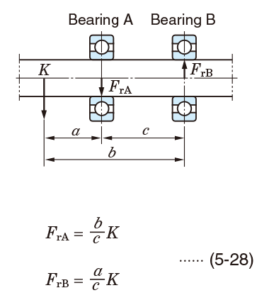
In this case with the pinon:
A - 35mm
B - 80mm
C - 45mm
Kt - 62961N from the calculation above (tangential only for now)
FrA = 80/45 * 62961 = 111930N
This just doesn't make sense to me. How is the tangential force on the bearing nearly double that of the force on the gear tooth?
On the stock motor that this transfer case is from, the engine torque is about 300nm, then that goes through 1st gear and the final drive (which this transfer case is directly coupled to). So 3000 * 12ish = ~3300 and bearing A in the stock TCASE is only rated for 105,000N so now way stock torque is already creating forces over the bearing rating.
Am i on the right tract here guys? I must be missing something.
Any and all help is much appreciated.
I have a computer science background (this is my first big personal ME project)... so don't be too harsh on me heh.
I have a hypoid spiral bevel gear set that I am designing a new case for. The original case is very cheap cast aluminum that breaks very easily. This piece is a transfer case thats send power from the front of the car to the rear wheels.
I am working on calculating the gear tooth forces and then calculating the forces on the shafts. I have already prototyped the case for testing gear fitment but want to calculate the forces and then do some FEA on my prototypes before I go any further.
Here is a picture to get an idea of what I am talking about. The torque is input through ring gear (yes you read that correct) and output through the pinon.
I have been using the following website to calculate the gear teeth forces :
Specifically this table... from my understanding of bevel gears the tangential force is calculated the same way for all types and only the axial and radial change based upon whether its straight, spiral, zerol, etc.
Ignore the values in this table, they are just example values.
I did some calculations by hand in excel, but found out the KHK Gears website had an online calculator using the exact table above. I ran a calculation with ~3300nm of input torque on the ring gear (or 1000nm output on the pinon, 3.31 ratio). I came up with the following:
Now that I knew my tangential, radial and axial gear tooth forces I could calculate the actual forces on the bearings. To do that I use the following two websites:
(I used page 3 to calculate the tangential, radial and axial and then combined)
(This I used to just get an idea on the tangential forces on the bearings but also has good info on calculating combined)
This is where I started second guessing myself. The gear tooth forces seemed pretty realistic to me and I found the same math on a lot of different websites indicating its pretty standard stuff. I did however have some trouble finding how to calculate the forces on the bearings. I know I need to calculate the tangential, axial and radial on each of the bearings, then I can calculate the combined radial load using those 3 and use that in my FEA sim along with the axial load.
But first I wanted to get an idea of the tangential forces on the bearings.
In this case with the pinon:
A - 35mm
B - 80mm
C - 45mm
Kt - 62961N from the calculation above (tangential only for now)
FrA = 80/45 * 62961 = 111930N
This just doesn't make sense to me. How is the tangential force on the bearing nearly double that of the force on the gear tooth?
On the stock motor that this transfer case is from, the engine torque is about 300nm, then that goes through 1st gear and the final drive (which this transfer case is directly coupled to). So 3000 * 12ish = ~3300 and bearing A in the stock TCASE is only rated for 105,000N so now way stock torque is already creating forces over the bearing rating.
Am i on the right tract here guys? I must be missing something.
Any and all help is much appreciated.