Continue to Site

Eng-Tips is the largest engineering community on the Internet

Intelligent Work Forums for Engineering Professionals

  • Congratulations KootK on being selected by the Eng-Tips community for having the most helpful posts in the forums last week. Way to Go!

I Beam Section Moment

Status
Not open for further replies.

AAA1993

Civil/Environmental
Mar 9, 2023
18
Hi all, I wanna verify the model and therefore I checked whether the bending moment is same as theoretical value and found that there is huge difference.

SI unit defined: force=N, length=mm

Beam length:5000mm, flange width=100mm

Input load=200kN/m [I modeled as 19608N point load at each mesh node (100mm mesh, total 51 node)]
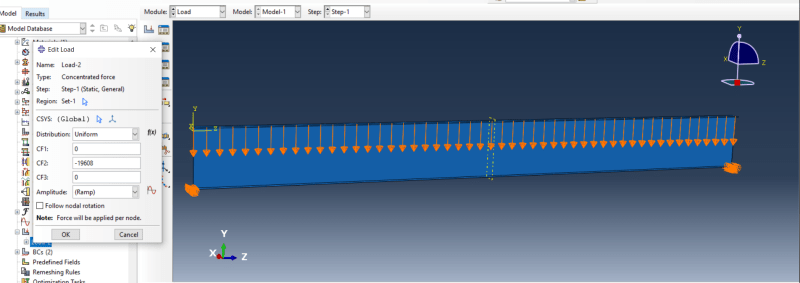
load_v2_wk1ngx.png


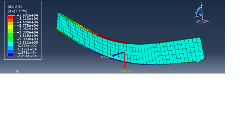
Bending moment should be SM2 and I understood SM2 is moment per unit width in Abaqus.

SM2_qli5au.png


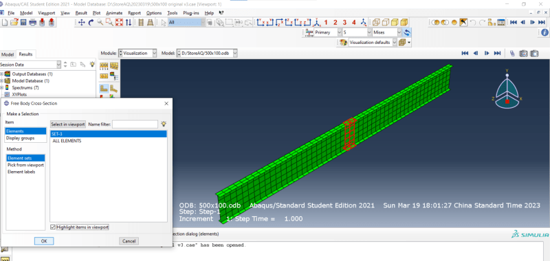
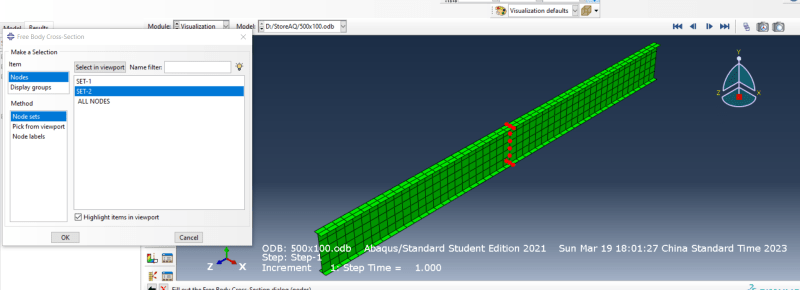
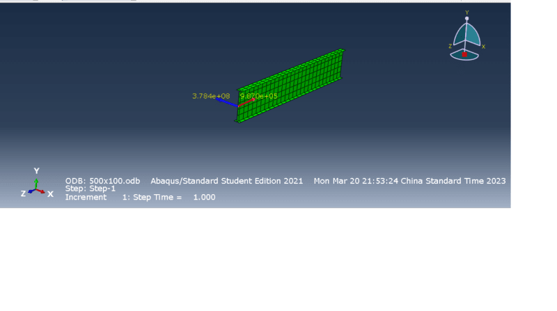
I tried to cut free body diaphragm near middle span(see below image)
free_body_jtjsnf.png


The moment is 6.832e3.

The theoretical bending moment value should be 625kNm which is different from abaqus. But the theoretical reaction force is close to abaqus value.

I just wanna ask did I extract wrong moment or the model is wrong.

Thanks all
 
Replies continue below

Recommended for you

It’s likely a matter of units or incorrect reading from Abaqus but the mesh should be significantly refined too. Can you share the .cae file ?
 
Limit the view to the top flange only (using the Replace Selected tool), then enable view cut and add free body computation. Note that you will have to add SF to output requests first. Multiply the result by the width of the flange (SM is moment per unit width) and you will get an agreement with the analytical solution.
 
Dear FEA way,

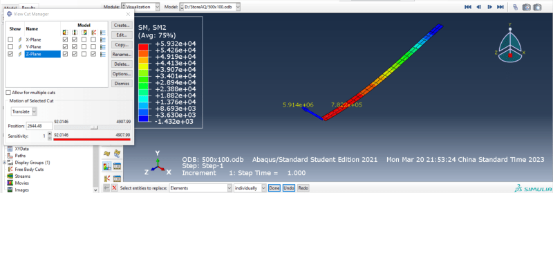
Thank you very much. I tried and top flange is about 591kNm (see below image)
top_flange_cut_slrmtq.png


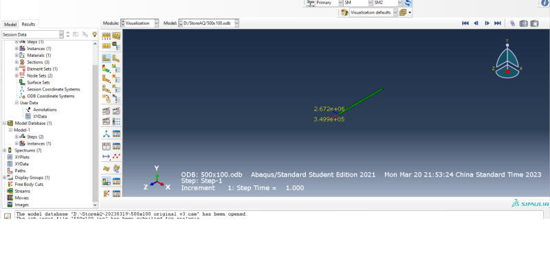
I did the same for the bottom flange and whole section, and found the moments are different.

bot_flange_cut_ak7itv.png

full_body_cut_uxssel.png


So we normally take the value at top flange free body cut as bending moment instead of whole section free body cut?

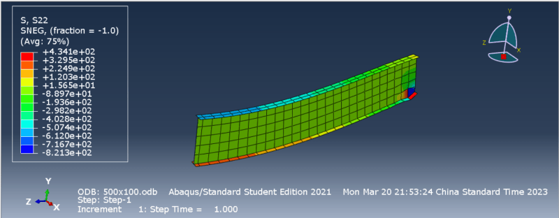
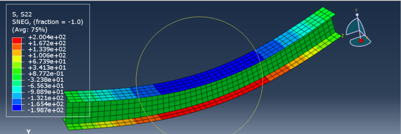
Also, the optimal goal of my task is to get the stress at tension flange (which should be bottom flange in this case), but i found that top flange has more stress than bottom flange. In ideal case, the stress at bottom and flange should be similar since the I section is symmetric. So, I just wonder if there is any problem in my model but other things seem fine to me.
S22_v3_idw7dg.png


Thanks for your help again!!
 
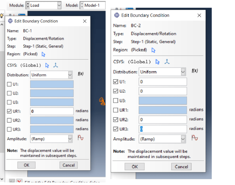
It’s a matter of boundary conditions. To agree with the assumptions of the analytical solution, one support should have all degrees of freedom apart from UR1 fixed and one support should have only U3 and UR1 free. Then not only normal stresses in the flanges will be symmetric but also the moment displayed by the Free body cut tool will be correct.

I would also replace those concetrated forces with equivalent pressure load applied to the whole surface of the top flange.
 
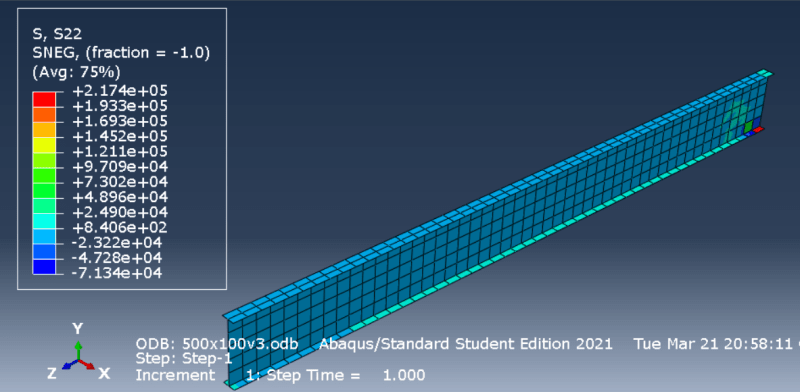
Thanks again FEA way. However I tried the above setting and found the results kind of strange.
setting_20230321_b9adwn.png

s22_20230321_hcq7qo.png

free_body_20230321_awk1vt.png


Stress concentrated at the side where UR1 is fixed.

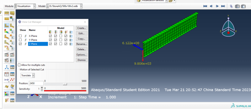
Also, I tried set U1=U2=0 at two end(bottom flange and web), the result seems normal, but the moment magnitude still too large (6.122e+8 Nmm per unit width x100mm= 61220kNm)

s22_U1_U2_0_20230321_v3jyfl.png

free_body_U1_U2_0_jsrzss.png


And I did the same practice for 500x400 I beam, the moment per unit width is also 6.122e+8, if I multiple it by 400mm, I will get 244880 kNm which is strange because the loading and length of beam are the same in the model. The moment should be same too.

I think I did something wrong but dont know the problem.
 
or I dont have to multiple flange width if I get the moment from free body cut?
 
That's not what I meant. The supports should be defined this way:
1) U1=U2=U3=0 and UR2=UR3=0
2) U1=U2=0 and UR2=UR3=0

This way one support works like a roller support and both allow in-plane rotation like hinged supports.
 
Thanks FEA way again.

I just wonder if I dont have to multiple flange width if I get the moment from free body cut? Becuase I found that moments from free body cut are the same for different section with same load and length.
 
No, what you get as a moment from free body cut in this case is in a very good agreement with the theoretical result. Bending moment, unlike stress and deflection, does not depend on the cross-section. The formula for maximum bending moment for a simply-supported beam of length L subjected to uniformly distributed load q is M=(q*(L^2))/8.
 
Status
Not open for further replies.

Part and Inventory Search

Sponsor