pv_mkk
Mechanical
- Jun 11, 2015
- 24
Vessel info :
-Design as per ASME Sec.VIII Div.1
-SS304
-Shell 12mm ; 3500mm TL-TL; ID2500mm
-Ellip Head 12mm
-Vertical
-D.P. @6Bar/FV ; Test P. @7.8Bar
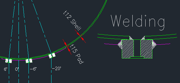
Sight glass base frame is designed following sight glass vendor's catalog by using model that can retain pressure to 10Bar.
And I also increase thickness from the catalog.
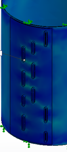
Sight glass arrangement as you see in the picture below.


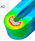
But FEA result showed that at sharp edge of round corner of sight glass base frame has stress around 600-700MPa and deformation occured around 2.5mm

Can I still fabricate this vessel from this design?
Or I cannot use this sight glass model from this vendor?
Please kindly suggest. I never designed this kind of sight glass before. How can I make sure to my customer that the design is safe.
Thank you very much.
-Design as per ASME Sec.VIII Div.1
-SS304
-Shell 12mm ; 3500mm TL-TL; ID2500mm
-Ellip Head 12mm
-Vertical
-D.P. @6Bar/FV ; Test P. @7.8Bar
Sight glass base frame is designed following sight glass vendor's catalog by using model that can retain pressure to 10Bar.
And I also increase thickness from the catalog.
Sight glass arrangement as you see in the picture below.


But FEA result showed that at sharp edge of round corner of sight glass base frame has stress around 600-700MPa and deformation occured around 2.5mm

Can I still fabricate this vessel from this design?
Or I cannot use this sight glass model from this vendor?
Please kindly suggest. I never designed this kind of sight glass before. How can I make sure to my customer that the design is safe.
Thank you very much.
