Navigation
Install the app
How to install the app on iOS
Follow along with the video below to see how to install our site as a web app on your home screen.
Note: This feature may not be available in some browsers.
More options
Style variation
-
Congratulations MintJulep on being selected by the Eng-Tips community for having the most helpful posts in the forums last week. Way to Go!
You are using an out of date browser. It may not display this or other websites correctly.
You should upgrade or use an alternative browser.
You should upgrade or use an alternative browser.
I have an European print in which t
- Thread starter Heming
- Start date
- Status
- Not open for further replies.
- Thread starter
- #3
- Thread starter
- #5
Heming,
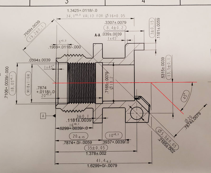
I'm not sure I can even tell what the second angled feature is supposed to be from this view, theres a diameter dimension and tolerance but no opposing side from which to measure a diameter? I do see some pretty terrible formatting, and a lone Datum Feature Symbol, but no geometric tolerances (ie: position). From the view you have shown, there is no requirement for these two features (or several of the features shown) to be at any particular orientation/location relative to each other unless as greenimi noted there is some applicable general tolerance/note which covers it.
I'm not sure I can even tell what the second angled feature is supposed to be from this view, theres a diameter dimension and tolerance but no opposing side from which to measure a diameter? I do see some pretty terrible formatting, and a lone Datum Feature Symbol, but no geometric tolerances (ie: position). From the view you have shown, there is no requirement for these two features (or several of the features shown) to be at any particular orientation/location relative to each other unless as greenimi noted there is some applicable general tolerance/note which covers it.
- Thread starter
- #7
Just not enough info available from this print. For your own good: This unbelievable conversion (x25.4) will kill you.
Stay with metric only. You are taken a simple part print and are making a monstrosity out of it almost impossible to to make this part. If you are making parts designed in metric than stick with metric. Conversions like shown on your print will kill you.
Stay with metric only. You are taken a simple part print and are making a monstrosity out of it almost impossible to to make this part. If you are making parts designed in metric than stick with metric. Conversions like shown on your print will kill you.
mfgenggear
Aerospace
conversions from metric to English and vice a versa is common.
I would suggest to contact the originator or the customer and ask them the required true position.
the missing requirement is the true position on center line of the part. if that fails because the dimension .7559 has a +/- .0039 inch
total tolerance of .0078 . I would cut the tolerance in half and use true position of .004 held on center line.
- Thread starter
- #10
Precision: DIN ISO 2768-mH.
general tolerances are based on customary workshop accuracy, not part function.
The tolerance is the total width of the tolerance zone. Thus a tolerance of 1 mm is usually ±0.5mm
m = Middle tolerance. not Fine or Coarse- linear dimensions, angular dimensions
H = finer grade - straightness and flatness, circularity, cylindricity, parallelism ( numerical value of size or flatness/straightness, whichever is greater) , perpendicularity (H for 100 mm long features 1.2mm ± 0.6, symmetry , coaxially
- Thread starter
- #12
Burunduk
Mechanical
- May 2, 2019
- 2,580
I agree with mfgenggear that the best way is to contact the customer and ask them what is acceptable.
I also agree with chez311 that the dia. 20 mm angled feature looks unclear. Is this some sort of arc in a true view? Can you even derive a center axis from it on the actual part?
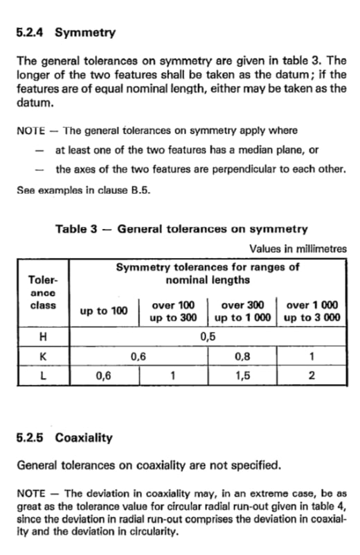
If you want to go by the ISO general tolerances anyway, then the only location controlling geometric tolerances listed in ISO 2768 are symmetry and circular run-out. You may try to treat the deviation from axis-coplanarity that you want to control as symmetry (note that this is ISO symmetry, not the ASME Y14.5 kind of symmetry). The only value listed for the H class is 0.5, regardless of the length of the feature. You use the longer feature as the datum, but you have several to choose from. The M18 thread looks like a good candidate. This is from ISO 2768-2-1989 that remains the latest:

- Thread starter
- #14
Burunduk
Mechanical
- May 2, 2019
- 2,580
Hi Heming,
This also seems to be how it is dimensioned. The 20 mm "bore" is only a small curved surface of 10 mm radius. I don't think you'll be able to determine the axis of that thing to control its position. A proper print would have it defined by basic dimensions and a profile of a surface applied to it.
This also seems to be how it is dimensioned. The 20 mm "bore" is only a small curved surface of 10 mm radius. I don't think you'll be able to determine the axis of that thing to control its position. A proper print would have it defined by basic dimensions and a profile of a surface applied to it.
- Thread starter
- #16
I got used to basic dimension and true position. But ISO seems or this specific customer have different way to define the relationship. What I don't like is that my CMM guy could not intersect the two centerlines then he converted 3D to 2D (project them into an artificial plane) to make them intersect. I told him we need the feedback how far these two centerlines apart of each other.
Heming,
Good luck with deriving a reliable axis from that partial cylinder. In ASME it would not be allowed to apply a position tolerance to this feature, as it is not a FOS and is lacking opposed points. Not sure about ISO, but the same issue will arise with deriving a reliable axis no matter the standard. Profile is what is needed to control this feature reliably.
Good luck with deriving a reliable axis from that partial cylinder. In ASME it would not be allowed to apply a position tolerance to this feature, as it is not a FOS and is lacking opposed points. Not sure about ISO, but the same issue will arise with deriving a reliable axis no matter the standard. Profile is what is needed to control this feature reliably.
- Thread starter
- #18
mfgenggear
Aerospace
it's easier to machine than to inspect. however it should be doable with CMM, edit it takes a lot of hits, and proper programing
- Status
- Not open for further replies.
Similar threads
- Question
- Replies
- 11
- Views
- 5K
- Locked
- Question
- Replies
- 5
- Views
- 3K
- Locked
- Question
- Replies
- 4
- Views
- 568
- Replies
- 23
- Views
- 7K
- Question
- Replies
- 17
- Views
- 7K

