Continue to Site

Eng-Tips is the largest engineering community on the Internet

Intelligent Work Forums for Engineering Professionals

  • Congratulations KootK on being selected by the Eng-Tips community for having the most helpful posts in the forums last week. Way to Go!

I need your vote for a new Rotary HCCI engine ! 4

Status
Not open for further replies.

RodRico

Automotive
Apr 25, 2016
508
Fellow engineers,

This post promotes my design, but it's also informative for those curious about new developments in engine design, so I hope it's OK. Please accept my apologies if not.

I have submitted my patent pending design for a "Hybrid Miller Cycle Rotary HCCI Engine for RQ-7 Class Drones" in the "Create the Future" contest. You may find it by googling the engine name above or by visiting
Preliminary analysis indicates power density (3 HP per pound) and efficiency (45% with 0.300 BSFC) comparable to a turbofan when operated at full equivalency. When operated in Low Temperature Combustion (LTC) mode, the engine still produces nearly 1 HP per pound but creates very few emissions. Because of its small 10" diameter and 6.5" thickness, multiple engines can be arranged in a clover-leaf pattern around a common shaft to yield 380 HP in a 24" by 6.5" volume. Another set of engines can be arranged behind the first to yield 760 HP in 24" by 16" volume. Note it's not mechanically efficient to add a third engine set due to limitations in my design.

I would greatly appreciate your support of my contest entry. Viewing my entry helps, but voting for it (which requires simple e-mail verification) helps even more. As it stands, I'm only one vote ahead of a "free energy" device ! That's just wrong ! Please circulate the link as widely as possible and encourage all your engineering friends and colleagues to help me win this contest! If I win the contest 100% of the money will go to funding 3D modeling of CFD/Combustion/Heat Loss by a consultant.

Thank you very much for your time and any support you can offer. If you have questions or comments, please post them here or on the contest site and I will answer them to the best of my abilities. I view criticism as being more valuable than praise when it comes to design, so don't hesitate to challenge my design (but please keep it respectful per normal engineering tradition).

Respectfully,

Rod Newstrom

P.S. Some may wonder why I targeted my contest entry at military drones. I would have preferred to emphasize the efficiency and low emissions qualities of my engine when operating in Low Temperature Combustion (LTC) mode. I targeted the military application instead because the administration wants to zero funding at the DOE/ARPA-E (who would normally fund such advances) while simultaneously increasing military budgets. I mention the RQ-7 drone, an unarmed surveillance drone, specifically because my engine fits in the volume and weight envelope of its current engine (the AR-741 Wankel), and the Army issued a Request For Information in 2016 for a replacement engine.
 
Replies continue below

Recommended for you

RodRico,

The engine you are competing against, the successor to the Midwest/Norton rotary , basically only has 3 moving parts not counting the accessories. and still costs over $10,000.0 , with all of the parts in your engine , how are you going to get to a manufactured cost that competes with this engine ?
If not the only other path is efficiency.
B.E.

You are judged not by what you know, but by what you can do.
 
enginesrus,

How can you assess my tribological design based on the information provided? You must be a seer! :)
Yes I have a lot of parts. I have a lot fewer than a modern 6 cylinder four stroke, however. Note my pistons are about the same weight as valves in a conventional engine and are driven by cams.
Estimated performance is given at My preliminary analysis shows 95 HP at 7800 RPM in 31.4 pounds including all accessories.

Entry for this year's context closed on 1 July. You should enter next year!

I love looking at engine concepts! Is yours online anywhere?

-----------------------------------------------------------------------------------

berkshire,

One reason I chose the military drone market as an entry point is their tolerance for cost. They currently pay over $25,000 for a 100 HP engine not including the accessories that are built into my motor. The real challenge will be in the commercial markets such as the 15 million unit per year scooter market (which I will target with a 6 cylinder version running in LTC mode producing about 1 HP/LB). My engine will be built on a 5 axis CNC machining center. Using this kind of technology, set-up is a major factor in cost, so the number of *unique* parts has great bearing. Though I have many parts, I don't have many unique parts, so I'm hopeful. I will certainly develop cost models before seriously considering markets beyond military UAVs.

Sorry for the delay in responding... I just got back from Europe and have been catching up on other things!

Rod
 
Bershire,

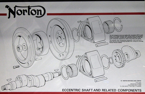
I did a bit of research on the Midwest/Norton rotary. Wikipedia has scant information ( but does mention the Midwest is closely related to the Norton for which more information is available. Here's a picture of the Norton's guts...

13498906235_34cb43bcaf_nevqsm.jpg


I see a lot more than three moving parts in that image, and that's of the engine alone sans accessories such as the oil pump, starter, and generator. Eliminating accessories from the comparison is silly IMHO as they are all part of the final system. My engine as shown includes all necessary accessories except the battery and fuel tank, and I feel part of its attractiveness is the synergy attained between the accessories and the ICE components proper. Granted, my engine isn't running yet (much less demonstrating the desired performance), but the *concept* stands up well under comparison in my humble opinion.

In prior comments I mentioned that my original objective was to fix the shortcomings of the Wankel such as in my 1993 RX-7. The more I learned, the more dire the outcome seemed; while it's fantastic in terms of power per unit weight and volume, the engine just has too many shortcomings where emissions, reliability, and efficiency are concerned. I won't bother detailing the issues here, I'll simply point you to this excellent report by the Army Research Lab: The report was generated as part of the Army's long history working to improve the Wankels used on air vehicles such as the RQ-7 drone. While the titular subject of the report is heavy fuel operation, it contains a lot of great discussion of the Wankel in general.

Rod
 
Rodrico,
The AR-741 Wankel that you cite was developed from the Midwest rotary which in turn was developed from the Norton rotary . I should of course mentioned that the 3 moving parts are of course assemblies not just individual components.
B.E.

You are judged not by what you know, but by what you can do.
 
<<<<<I have a lot fewer than a modern 6 cylinder four stroke, however. Note my pistons are about the same weight as valves in a conventional engine and are driven by cams>>>>

So then your pistons are driven by cams? Most IC engines I have been around the pistons are being driven by combustion pressure and then the pistons are driving a crankshaft. Oh a special note the radius of the crank throw turns that pressure to torque. A cam in a normal piston 4 stroke engine is something you try not to over load with pressure.
It will not matter what your cam follower system is that is going to be the weakest link and along with the crazy high pressures needed to create torque into that cam system. So how is the proto type going? Any parts made yet?
 
Enginesrus,

LOL! You're the master of syntax!

In the spirit of your piston comment...
What drives *your* pistons during start, compression and exhaust?
What parts *do* you try to overload?
Torque = BMEP x Displacement x PPR/75.4

Prototypes follow analysis. The cam loading is easy to assess, and it's fine. My consultant (who has worked with Mazda, Honda, and Liquid Piston during engine development) just sent me his mid-task report a few days ago in which he performed feasibility and risk assessments. He found no mistakes and his error analysis said I was with a few percentage points one way or the other. His biggest concern was port fill time which drove him to suggest I increase port height. I asked whether this engine was viable and worth pursuing further, and he replied in the affirmative adding "this is pretty exciting." He's now moving on to independent bottoms up analysis just to be sure. We also discussed next steps, and I am now making the simplified break-out models we'll need for 3D analysis (chemical kinetics, CFD, heat transfer, cooling). Only once everything is tweaked up in the 3D analysis will metal be cut, and it won't be an engine, but critical experiment fixtures, instrumentation, and engine subsystems. I'll start building the shop and my son (also an engineer) will be tweaking the mechanical design for manufacturability while our consultant is working the 3D analysis. I expect experiments and design refinements will occur in 2018 and the first prototype in 2019.

Rod
 
May I suggest some some 1D modelling of a single cylinder? Some of the innovative features of your engine are based on invalid assumptions around P/V and T/Theta. (The contra-pistons, stepped bore and different stroke/piston motion are unnecessary)

A lot of effort goes into dead-end designs for lack of basic consultation and intervention at the concept design stage. OPOC and Achates are good examples.

je suis charlie
 
gruntguru,

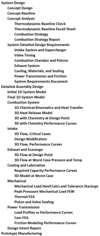
My consultant identified nothing wrong in my work, and he's quite experienced; he helped design Mazda's SkyActive, LiquidPiston's engine, and an unspecified engine for Honda. He's also worked with a number of well known shops including WERC, ESI, CdAdapco, Mahle, and AVL. That being said, we *do* plan to do 1D followed by 3D analysis. At the bottom of this message is a screen grab of the plan (sans hours and costs) we're working to.

My consultant has checked all my work and found it to be complete and "within plus or minus a few percentage points." As I noted, he's currently doing an independent top-down analysis just to be sure. Assuming his conclusion regarding my analysis holds up after he finishes his own top-down analysis, we'll move into more sophisticated modeling and simulation.

No offense, but I'm going to have to go with my consultant's opinion over yours. It's what I pay him for. He has the entire set of design and analysis files which you don't have. I'm confident you know what you're talking about when it comes to engines, so I assume the errors are being introduced in my poor communication of the design.

FYI, I can't find a free copy of this paper, but you might find Morton, R., Riviere, R., and Geyer, S., "Understanding Limits to the Mechanical Efficiency of Opposed Piston Engines," SAE Technical Paper 2017-01-1026, 2017, doi:10.4271/2017-01-1026 illuminating. In this paper, the authors (who work for Volvo) say:

"In the case of the opposed piston engine, it is important to keep in mind that the P-V diagram applies to the gas volume, while the standard indicator calculations compute the volume from the piston displacement. In conventional single piston architecture, the change in volume is simply cylinder area times piston displacement. In the opposed piston design, the two pistons may be moving at different rates and directions, but there is only a single working volume and pressure. The indicator diagram and P-V diagram are different in this case... The difference between the loads on the two cranks is not due any difference in pressure on the pistons, but the transform of thermodynamic work to mechanical work for each piston-rod-crank system... The work is not evenly distributed between the two cranks because of this phasing, even if the basic geometries are similar (stroke, rod length, piston area, offsets). In a typical case with crank phasing between 10 and 20 degrees, the minimum volume does not occur at TDC for either crank, but at a point after TDC as the leading piston starts to accelerate out of the cylinder and before the trailing piston, which is still traveling inward in the cylinder, reaches its TDC. Note that the sign of the work terms is not necessarily the same at any instant in time. Since expanding gas work is positive, the positive x direction is outward from the center of the cylinder for both pistons. Thus inward motion of the pistons consistent with compression results in negative work while outward motion results in positive work. This piston work translates into positive (or negative) shaft work by contributing torque to the respective crankshaft. The trailing crank is producing a negative torque throughout the pressure rise until about the location of peak cylinder pressure, and due to kinematics, produces less torque throughout the cycle... The conventional approach to opposed piston engine design is to simply sum the resultant torques from each crank system. It must be recognized that these negative torque excursions on the trailing crank are clearly subtractions from the torque of the leading crank. There are additional losses such as the friction losses that are a function of the absolute loads on the components. The friction of the connecting gear train is higher due to the two cranks fighting each other with the transmitted torque being the sum of the instantaneous driving and restraining torques."

The authors are describing what I have attempted to communicate, albeit poorly.

Rod

The plan:
PLan_s3ldaf.jpg
 
Yes the quote is a correct analysis. However, with the exception of variable compression, there is nothing in the OP design with or without stepped bore (in terms of PV and work) that could not be accomplished with a single piston - especially one which is cam driven.

je suis charlie
 
We all will be waiting for the proto type and the results of hundreds of hours of dyno time.
 
Rotary engine:
One in which the crank is stationary and the cylinders revolve around the crank.
Rotary engine:
An engine that uses a rotor in a chamber rather than pistons and cylinders. Some similarities to a vane pump.
One word, two completely different meanings. Both valid.

Bill
--------------------
"Why not the best?"
Jimmy Carter
 
waross, Its more of a radial engine he has, but I guess they don't teach that subject. So ?? Nomenclature is at a loss.
 
A rotating radial? OK
Can I call V type engines truncated radials?
More fun with words. grin

Bill
--------------------
"Why not the best?"
Jimmy Carter
 
Y'all better go edit Wikipedia. They call rotating cylinder radials "rotary" and so do the US and international patent classification systems. Mine is in the rotating cylinder class. I'm an RX-7 owner. I'm familiar with what the public generally calls a "rotary." The literal definition is wider, however.
 
Waross,

As long as the cylinders rotate around the central shaft, you can call your v-type engine a "rotary." You'll need a pretty large balance with a v-type cylinder arrangement, however. 😁

Rod
 
I said radial, not rotary.

Bill
--------------------
"Why not the best?"
Jimmy Carter
 
SkynexDrones,

All I have at present are renders from Solidworks. I have made a number of refinements since I wrote the contest entry based on inputs from my engine design/thermodynamics consultant. The new engine *always* runs in Low Temperature Combustion (LTC... peak temp below 2150K) to keep NOx down and never exceeds 225 bar pressure. I'm now in the detailed design phase of a prototype engine having 50cc displacement and producing roughly 7 lb-ft torque and 3.5 HP at 2,226 RPM with >50% efficiency at up to 15,000 foot altitude. The whole thing should be under 5" in diameter and 3" thick (including everything except the fuel tank and electric motor/generator I mentioned in my contest entry). The RPM probably seems a bit low to most, but it is near typical propeller speed on a real aircraft and yields 52 MPH directly driving a 100/90R14 scooter tire without use of a transmission. I'll post pictures as the build progresses. It will be a while... hopefully before year end.

Rod
 
Very impressive RodRico. When do you anticipate completing the prototype? Pictures are always helpful. Some of us are more visual than others ;) I must also add, a picture is worth a 1000 words. A bit difficult to conceptualize everything without a picture.

SKYNEX GLOBAL DRONES | WORLD'S PREMIER DRONE STORE
P: 1-888.575.9639
E: mail@skynexglobaldrones.com
 
"I'm now in the detailed design phase of a prototype engine having 50cc displacement and producing roughly 7 lb-ft torque"
So a BMEP of 47.7 Bar? (24 Bar if 2 stroke) So I assume it will execute multiple thermodynamic cycles per revolution?

"3.5 HP at 2,226 RPM with >50% efficiency"
>50% indicated efficiency will be a record for an engine this size. >50% brake efficiency will transform the planet.

Where do I invest? [bluegreedy]

je suis charlie
 
Status
Not open for further replies.

Part and Inventory Search

Sponsor