Continue to Site

Eng-Tips is the largest engineering community on the Internet

Intelligent Work Forums for Engineering Professionals

  • Congratulations KootK on being selected by the Eng-Tips community for having the most helpful posts in the forums last week. Way to Go!

I need your vote for a new Rotary HCCI engine ! 4

Status
Not open for further replies.

RodRico

Automotive
Apr 25, 2016
508
Fellow engineers,

This post promotes my design, but it's also informative for those curious about new developments in engine design, so I hope it's OK. Please accept my apologies if not.

I have submitted my patent pending design for a "Hybrid Miller Cycle Rotary HCCI Engine for RQ-7 Class Drones" in the "Create the Future" contest. You may find it by googling the engine name above or by visiting
Preliminary analysis indicates power density (3 HP per pound) and efficiency (45% with 0.300 BSFC) comparable to a turbofan when operated at full equivalency. When operated in Low Temperature Combustion (LTC) mode, the engine still produces nearly 1 HP per pound but creates very few emissions. Because of its small 10" diameter and 6.5" thickness, multiple engines can be arranged in a clover-leaf pattern around a common shaft to yield 380 HP in a 24" by 6.5" volume. Another set of engines can be arranged behind the first to yield 760 HP in 24" by 16" volume. Note it's not mechanically efficient to add a third engine set due to limitations in my design.

I would greatly appreciate your support of my contest entry. Viewing my entry helps, but voting for it (which requires simple e-mail verification) helps even more. As it stands, I'm only one vote ahead of a "free energy" device ! That's just wrong ! Please circulate the link as widely as possible and encourage all your engineering friends and colleagues to help me win this contest! If I win the contest 100% of the money will go to funding 3D modeling of CFD/Combustion/Heat Loss by a consultant.

Thank you very much for your time and any support you can offer. If you have questions or comments, please post them here or on the contest site and I will answer them to the best of my abilities. I view criticism as being more valuable than praise when it comes to design, so don't hesitate to challenge my design (but please keep it respectful per normal engineering tradition).

Respectfully,

Rod Newstrom

P.S. Some may wonder why I targeted my contest entry at military drones. I would have preferred to emphasize the efficiency and low emissions qualities of my engine when operating in Low Temperature Combustion (LTC) mode. I targeted the military application instead because the administration wants to zero funding at the DOE/ARPA-E (who would normally fund such advances) while simultaneously increasing military budgets. I mention the RQ-7 drone, an unarmed surveillance drone, specifically because my engine fits in the volume and weight envelope of its current engine (the AR-741 Wankel), and the Army issued a Request For Information in 2016 for a replacement engine.
 
Replies continue below

Recommended for you

I could use an engine similar to that for a project I am working on , however I only need 45 hp not 90
You can keep me posted on here as to your progress . I have seen and investigated a great many engines that look promising , only to find that they fail to deliver promised horsepower and weight savings when actually built.
B.E.

You are judged not by what you know, but by what you can do.
 
I answered my own question ... "If I win the contest 100% of the money will go to funding 3D modeling of CFD/Combustion/Heat Loss by a consultant." In other words, this is currently a CAD exercise.

But the question was more of a shot across the bow before firing the main volleys.

This thing has A LOT of finicky little bits and pieces. It has A LOT of opportunities for leakage past seals. Those hydrodynamic cam followers are going to have a lot of friction. It has A LOT of surface area relative to displacement which means lots of heat loss. All of this means the claimed efficiency is a pipe dream. The claim of low emissions is also a pipe dream.

Why should this mechanical layout be any better at operating in HCCI mode than any other (e.g. conventional) layout is?
 
Very nice rendering and lots of effort in detail design. Unfortunately Brian is spot on.

Why the stepped bore in the power cylinders?

Does the rapid compression piston really have a stroke of 0.048 (1/10th of the other piston?)

I assume the dimensions are inches? If so, the use of mixed unit systems (masses in g) is not recommended.

je suis charlie
 
Berkshire, I will develop different sizes based on demand, but only *after* this one is in production. I estimate that will take between 3-5 years, and that assumes it's funded (DARPA, ARPA-E, or private investors) and everything goes well. Yes, there are a ton of "new engine designs" out there that turn out to be rubbish. In my experience, this is due to publication before formal analysis (much less prototype) by non-engineers. I am an engineer, and I spent several years after the concept was finalized performing mechanical design and analysis (tolerances and FEA) as well as thermodynamics and inertial loads (Excel). Even then, I feel I am publishing early, but I got an estimate for the next phase of analysis (which has to be done in KIVA to be accepted by the HCCI community), and it's too much for me to bear without investment. I can't get investment without publishing my work thus far, of course, so it's a Catch-22 of sorts. I'm not hoping to win the contest so much as I am using it to publish. Many of the votes for my design come from respected experts in the field (who notified me by LinkedIn that they had voted).

--------------------------------------

Brian, Yes, it's still in the analysis phase. All new engines go through this phase.

The design may appear to have a lot of "finicky little bits and pieces," but relative to what? It has no valve train. No timing gear or belt, cam shafts, no valves, no valve spring retainers, no valve springs, no valve bushings, and no valves. Imagine how many "finicky little bits and pieces" a double overhead cam, 4 valve per cylinder, 4 cylinder engine has. Mine engine has less.

I have seal losses high on my risk register due to the tremendous pressure of HCCI at full power (equivalence 1). I am using soft steel rings on tool steel pistons in tool steel liners. Though I have a lot of rings, the total surface area is small, and my expansion stroke is very quick specifically to reduce the amount of time available for blow-by and heat loss. The side seals are another area of concern, but I am much more confident in them than I would be if I were using the kind of seals in the Wankel rotary.

I'd be interested in substantiation of your statement "Those hydrodynamic cam followers are going to have a lot of friction." Do you believe they result in substantially greater FMEP than the combination of sources I lack (valve train, piston skirts, oil pump, water pump) relative to a high performance engine running at 16,000 RPM (Ref 1)? If you wish to do some back of envelope work, the cam surfaces are micro-polished H-13 tool steel, the combined contact length is 1 inch, the average track length is 22.9 inches, the RPM is 7800, and the average pressure is 1142 pounds. Tell me what FMEP you came up with and we can compare and discuss our results.

My current analysis calculates heat loss in 0.5 degree steps using Hohenberg's heat transfer coefficient (which has been shown to be more accurate than Woschni's for HCCI (Ref 2, 3, and 4). These calculations incorporate the surface area of the combustion chamber. I want to do full 3D analysis using KIVA or similar because those models are well recognized in the community (DOE's HCCI consortium of academia, national labs, and industry). If I fail to obtain funding for the KIVA work, I will use Solidworks to do the same work with lower fidelity then conduct critical experiments and take measurements.

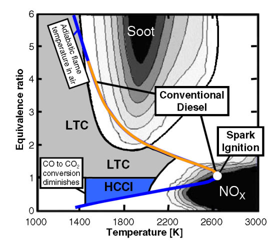
Claims of HCCI efficiency and low emissions in Low Temperature Combustion (LTC) mode are not mine, they are those of numerous researchers (Ref 5). I only claim low emissions when operating in Low Temperature Combustion (LTC) mode. In this mode, the maximum temperature is under 2100K, and this is low enough to prevent formation of NO2 (Ref 5). HCCI is also very efficient due to it's near instantaneous combustion, lack of a flame front, etc. (Ref 5). Granted, if my engine fails to perform according to my analysis due to heat loss, friction, etc., it won't attain the HCCI ideal. I have addressed your concerns in these areas in the above paragraphs.

If you are familiar with HCCI, you know what the challenges are: control of timing over a wide range of operating conditions, extreme pressure and ringing during full load operation, lean miss-fire limiting operation at low load and creating difficulty in starting (Ref 6). I address each of these in my contest submission. The core innovation of my design is the means by which I manage intake temperature by controlling supercharger pressure and the way I generate the auto-ignition event using an "ignition piston" such that the engine is insensitive to timing variance. If you read the literature, you will find nearly all HCCI research focuses on its use in existing engine designs, and the difficulties people are having is proof of the HCCI's incompatibility with those designs; big bores, uncontrolled intake temperature, and efforts to time combustion without any special means of initiating it are critical weaknesses. I set out to design an HCCI engine from the bottoms-up, and the resulting design is uniquely suited to HCCI combustion (hence the patent application).

-----------------------------------

gruntguru, the bores are stepped because that was required to ensure the reverse torque generated by the ignition piston during combustion is less than the forward torque of the expansion piston during combustion. This is only an issue during starting. Once the engine is running, the rotational inertia of the rotor is sufficient to prevent engine reversal.

Yes, the stroke of the ignition piston is very short. It's only purpose is to initiate ignition (it's my spark plug so to speak). When the ignition process starts, the larger piston is at TDC, so there's very little volume in the larger bore cylinder and the entire combustion chamber is defined by the smaller cylinder's volume. At this point, the charge temperature is just 100K below auto-ignition temperature. The ignition piston then performs a full stroke as the expansion piston begins moving slowly away to start its expansion stroke. The speed at which the expansion piston moves is determined by its bore vs that of the ignition piston and the radius of its cam versus that of the ignition piston, factors relating to prevention of reverse rotation. The final factor is the angle of contact (mechanical advantage) of the cams associated with each piston. Because the expansion piston has great advantage in its product of bore and lever length (cam radius), it can have a much more shallow cam angle with less displacement and lower speed. As a result of these dynamics, the expansion piston doesn't move far as the ignition piston rapidly approaches and the resulting compression ratio is very high, sufficient to cause auto-ignition. This is the most difficult part of the design to understand. Hopefully my explanation helps. Let me know if I failed.

Finally, you are correct, I shouldn't have mixed units. The weights were so small in pounds I switched the weight unit in Solidworks' "mass properties" dialog box to grams without thinking. I suppose I should have used ounces. Sorry !

Rod

------------------------------------------------------

Ref 1: Ricardo friction analysis of high performance engine: Slide 38, Ref 2: Heat transfer equation includes surface area: Ref 3: Hohenberg's heat transfer coefficient: Page 149, Ref 4: Heat transfer predictions in HCCI: Ref 5: HCCI Efficiency and Emissions: Ref 6: HCCI Challenges:
 
How does air get in and how does exhaust get out? Is there a cross-section or a schematic diagram? Is it a piston-ported two-stroke or it somehow a four-stroke? It's hard to follow from the CAD model how this is actually supposed to work.
 
My initial thoughts concur with Brian in this case. Apologies if this sounds rude or I am mistaken, but making claims without even the first attempt at a proper combustion analysis is out in the realm of powerpoint engineering, most in engine development consider that rather unethical. The irony is that its another HCCI project, aka the blackhole that many billions in corporate research have disappeared into due to powerpoint engineering.
 
Sorry but I really couldn't see much. And as far as a rotary engine, I thought I saw mention of pistons? Rotary engines don't have pistons.

 
BrianPeterson, I apologize for the limited drawings in the contest submission; they only allow 3 figures and 500 words. I'm in Europe right now responding by phone, so I can't get you more drawings. Words will have to do.

As I note in Figure 3, the outermost cylinder, which contains the air pump piston, is capped by a reed valve assembly through which pump intake air is drawn. The reed valve assembly has a sheet of spring steel laser cut to form 8 small reeds bound in an alumininum frame. On intake the 8 reeds open to pass air into the cylinder. On output, the 8 intake reeds close and another pair opens to pass pressirized air into chambers within the sideplates. Each sideplate contains two chambers, one for scavenge air and the other for intake charge air.

The engine has 36 pistons arranged as 12 radial sets of 3. Each set of three pistons form a modified Doxford Engine... esentially Junkers' opposed piston two-stroke with uniflow scavenging augmented by Doxford with an air pump piston. Modifications include deletion of diesel fuel injectors or spark plugs, non-symettric stroke of the opposed piston pair, and augmentation of the normal piston-gated in-cylinder ports with rotary side ports. The rotary side ports are essentially *ANDed* with the traditional ports. On intake, this allows seperate management of intake charge air and scavenge air. On exhaust, this allows continued expansion after the piston passes the in-cylinder port.

Exhaust blow-down occurs when the expansion piston reachs the end of it's stroke, well after it opened the in-cylinder exhaust port. At this time the exhaust sideports open and residual gas pressure escapes out the in-cylinder port, though the side port, and into the exhaust manifolds in the sideplates. The piston then pushes exhaust gasses out until it is just below the in-cylinder exhaust port. At this time, the scavenge side port opens and air travels from the pressurized scavenge chamber in the sideplate, through the sideport and in-cylinder intake port, through the combustion chamber, out the in-cylinder exhaust port, through the exhaust side port and into the exhaust manifolds of the side-plate.

Hopefully my many words have painted a picture that clarifies things. If not, I'll try again.

--------------

CWB1, Your apology for being rude is accepted. All you have seen is a contest entry. It is limited by the contest rules to 500 words and 3 illustrations. I have answered what challenges and questions I can here and really can't do much more at this point. I *do* have 24 months of extensive analysis backing my claims. If I send it to you, are you going to provide a resume with qualifications, sign the NDAs, then put a couple of months effort into checking it? That's what my consultant with advanced degrees in combustion, chemical kinetics, and heat transfer is charging me to review my work and perform independent analysis. He hasn't completed his independent analysis but he has completed his initial review of my work. He said it looked good and felt there was little risk of misrepresentation in going public at the time I entered the contest.

Yes, it would certainly be unethical to sell shares or seek investment without proper analysis. I have completed initial peer review and am funding independent analysis so I can present an ethical and trasparent proposal to investors. At this point, however, I'm not soliciting investment, I'm simply asking people in this forum to vote for my design so I can beat the numerous "free energy" machines entered in the contest. I don't feel that's unethical in the least.

Yes, I am intimately aware of the effort that's been put into HCCI and the poor results obtained thus far. Using your train of logic, I suppose everyone should stop trying because so many before have tried and failed. I explained why others have failed and how mine is different.

---------------

dicer, I happen to own a 3rd Gen RX-7 with the twin turbo Wankel Rotary. I also thought there was no such thing as a piston based rotary engine. Both the US and international patent classification systems as well as Wikipedia taught me otherwise. See
---------------

VE1BLL, My patent pending number is 62,485,227 with a filing date of April 20, 2017. It wont be available for public viewing for 18 months after filing per normal USPTO policy. See . I haven't received a number for my international filing under the Patent Cooperation Treaty (PCT). Am I supposed to get one or does that only happen upon national filing ?

Rod
 
So how does the fuel get in?

It doesn't look like it uses timed solenoid-fired direct-injection. Good thing, because I don't think one small enough for this has been developed.

Is it just squirting the fuel, untimed, into the scavenge air somehow?

If that's the case, some of it is going to get out the exhaust unburned - it's inevitable.

If it is somehow timing the fuel delivery to happen late in scavenging, you might have a chance of not having too much unburned fuel going through to the exhaust. The Bombardier SDI (semi direct injection) two-strokes that pre-dated their current direct-injection two-strokes were like this. Injection (via a more-or-less conventional automotive solenoid-operated injector) happened into the transfer port partway through the scavenging process with the hope that the early part of the scavenge was most likely to be the part that got out the exhaust but didn't have much fuel in it, and the late part of the scavenge with the fuel in it wasn't as likely to make it all the way across the piston and out the exhaust.

How are you handling atomisation/vaporisation? It's a problem area even for automotive 4-stroke spark ignition engines.

What about lubrication? This engine appears to be at least partially reliant on piston-porting. The means by which the piston rings cross the ports has historically been problematic. Some oil will inevitably end up going out the exhaust, or into the intake stream (or both). If adequate lubrication is supplied, the engine is an oil-burner and has exhaust emissions to show it. If lubrication is sparse, piston ring and cylinder wall life will be shortened. This was always a problem with the old two-stroke Detroit Diesel engines.

Now about that HCCI ...

Cold starting?

Light load, heavy load on the engine?

Pre-ignition due to running hot?

Or are you planning to use HCCI all the time simply because there's nowhere to put any spark plugs in places where you can get access to them ...

I just don't see this working out. Too many cylinders that are each too small, too many moving parts, too many surfaces that need to be sealed and lubricated and cooled, too many uncertainties what with both the mechanical arrangement and the proposed HCCI operation.

But, what do I know. I don't have the fancy thermodynamic and fluid dynamic analysis tools that your consultant does. I've only had about 15 or 20 motorcycle engines apart over the years, sometimes for fixing something that's broken, sometimes to prevent something from breaking before it does, sometimes in an attempt (not always successful) to "make faster" ...
 
Brian, the fuel injectors are unit type (100% mechanical) driven by axial cams incorporated into the side faces of the rotor. You can't see the cam lobes because the stroke is so small (because the fuel load is so small).

You seem to have missed the significance of separate side ports and chambers for scavenge and intake; it keeps the two processes separate and allows early injection into the intake air charge held in the intake chamber pressurized by the air pump.

The Junkers style opposed piston engines like mine don't work like those you've seen in motorcycles. There is no "crankcase" where the intake charge is stored, and oil is squirted directly onto cylinder walls and the bottom of pistons. Ports nearly circle the cylinder and are comprized of many slots with ring support metal between. Take a close look at some of modern opposed piston engines on the web (Achates, OPOC, etc).

My HCCI approach came first and is stated in general terms within separate patent claims because it is applicable to engines of all configurations. It was only after I developed that idea that I realized It simplified (if not enabled) construction of the rotating-cylinder radial engine.

My HCCI approach has a built in heater, extreme compression (even more than a traditional diesel). It also has an integral electric motor/generator. In arctic conditions, the engine is run without fuel until everything has exited cold-soak condition. Light load/lean burn is enhanced by excess compression and minimized by stopping fuel injection (and venting air pump pressure) into pairs of cylinders on opposite sides of the rotor such that the remaining cylinders can operate under heavier load. Full load HCCI is enabled by use of very small bore steel pistons which allow operation at very high pressure.

You keep coming back to how many parts and seals I have. I'm guessing you must absolutely hate V-12 overhead cam engines ! Hopefully you do acknowledge they work, however.

I've had more than a few engines apart on the bench over the years too. Most were motorcycles (Kawasaki Mach III, Yamaha RD-350, the venerable Honda 750, Kawasaki Z1, Pontiac 400 HO, and a Fiat 124 Spider. I ported and polished the RD-350 (making it unridable LOL!). The rest were just straight rebuilds with the occasional new cam, manifold, carb, and headers. I've always been an engine enthusiast but stopped working on them when they became cluttered with emissions controls and mods were all but banned in California.

Yes, there are a lot of uncertainties and issues I will be working through on my way to a working engine. Who knows what unforeseen challenges will pop up along the way. All the tools do is help us identify and address some of the basic issues in a computer (far cheaper than hardware builds) so we can focus hardware builds on other issues. As an engine builder you know how much simpler things become once you get the darned thing running, even if it's coughing and spitting a bit. Once running, you can start tuning.

I'll be the first to admit my engine may never make it to production for any number of reasons. I didn't come here to ask for money, I only asked for your vote in an inventors contest in which I am competing with ideas far less thought out than mine.

Do I get your vote ? :eek:)
 
Is my reasoning incorrect or is the tangential rate on the sliding surfaces 247 feet/second or nearly 15,000 feet per minute?

That seems high for a pin that will be constrained between two cam surfaces.
 
3DDave,

Yes, it's around 15,000 fpm assuming the average radius of the outer cam (0.304 ft) at 7800 RPM (130 rev/s). For comparison, the big end rod bearing of a Formula 1 engine has a diameter of about 1.34 inches or 0.11 ft. We know the crankshaft mains are larger, but I couldn't find the spec off hand, so let's go with around 2.5 inches or 0.208 ft. These engines run near 20,000 RPM (333 RPS), so the surface speed of the mains is around 13,000 fpm, not that much different than mine.

It's misleading to think of the cam follower being captive between the two surfaces of the cam track. Analysis indicates that the combination of centripetal and gas pressures are sufficient to hold the follower against the outer surface of the cam track even at 500 RPM. Thus the inner surface is really only being used during start, and there's no need for tight clearances between the follower and both track surfaces. Note, by the way, calculation of loads on the outer cam resulting from acceleration, gas pressure, and centripetal forces shows minimum 74% margin to material yield limits for H-13 tool steel.

By performing the surface speed calculation, you have discovered the rational for the hydrodynamic tilting pad followers (an independent claim in my patent); there are no roller bearings that will run at those speeds under high load. Even if there were, they'd be unattractive due to their cost and impact on reciprocating mass. As it stands, the outer piston assembly (expansion piston, pump piston, cam shaft, and both hydrodynamic bearings) only weigh about 50 grams. Note these issues of surface speed and reciprocating mass are not addressed in any existing patent of radial cam driven engines.

Note one of the earliest critical experiments on actual hardware will be stability, vibration, and friction of the outer cam at speed.

Rod
 
Detroit Diesels had a full ring of small ports all the way around the cylinder as you describe for yours. They still had tradeoffs between having enough lubrication and the oil consumption and emissions that came along with it, and piston ring and cylinder wear. They eventually had to give up with that engine design and go to 4-strokes.

What's the contact stress in your cam followers - particularly in view of your high compression ratio (and bear in mind that combustion will send peak cylinder pressure waaaay up)? Is it (approaching) point contact, line contact, or surface contact? To me it looks like line contact ...

The connecting rod to crank pin interface in a normal engine approaches surface contact.
 
Brian,

I suppose I may have issues with the ports. Nobody using them is reporting any, but I suppose that's to be expected. I guess I'll just have to find out for myself !

Did Detroit Diesel use separate paths for charge air and scavenge air ? If they didn't, I'm not surprised they had an emissions problem. I wonder if they didn't cut lubrication in order to try and mitigate that emissions problem. Do you have any useful links that will help me better understand the issues they found ?

I've completed comprehensive cam design and analysis. The analysis includes acceleration of the assemblies, gas pressure during all phases of operation including combustion at 7,000 psi (but only producing max 4200 pound force on the cam followers, 2100 pounds each, due to my small bore), and centripetal force. The surfaces undergo elastic deformation and the contact patch is 0.074 in2 at full load. This results in a minimum 74% margin to the yield limit of H-13 tool steel.

Rod
 
Detroit Diesel of course used only scavenging air (supplied by an external Roots blower - crankcase has oil in it) since fuel was supplied via direct-injection in those diesel engines.

The issue is that a wee bit of the oil supplied to the piston rings from the lubricated space underneath the piston, escapes into the port as the ring passes the port, and then on the subsequent scavenging operation, that oil gets blown into the cylinder. It will of course participate, at least partially, in the subsequent diesel combustion process, but Detroit Diesel was never able to get those engines to meet modern emission standards despite going to electronic unit injection in the later years.

As for issues "Nobody using them is reporting any" ...

The Detroit Diesel on-road two-stroke diesels went out of production decades ago and were never called upon to meet today's emission standards.
Many locomotive and ship engines still use the blower-scavenged piston-ported two-stroke diesel design, but they're not called upon to meet automotive emission standards. And those are very large low-RPM engines.
Modern fuel-injected spark-ignition two-strokes such as the Bombardier E-Tec snowmobile and outboard engines don't have to meet automotive emission standards ... and they have short service lives between rebuilds compared to anything automotive.
The various proposed opposed-piston two-stroke engines of various designs (OPOC etc) have yet to make it into production. I have the same reservations about those.

As for your safety factor to the yield stress ... what's your safety factor to the infinite-life fatigue limit?

Do you have radial clearance in that cam groove between the follower and each side of the groove? (Hope so, otherwise it will bind from thermal expansion!) Are load reversals going to cause "slop" and backlash leading to repeated impacts? This isn't necessarily a disaster; any valve mechanism in a 4-stroke using mechanical lifters (be it shim-bucket or manual threaded adjusters) has a repeated impact every time the cam hits the lifter and every time the valve gets set down on the valve seat ... but it requires careful design consideration to not be noisy and not break stuff.
 
Brian,

Your explanation finally set off the light bulb. Thanks !

After reviewing Achate's technical publication list ( ), I suppose it's obvious that emissions are a challenge in their opposed-piston two-stroke engine architecture, so I have to concede your point. They claim to meet emission standards (and have broadly published their test results), but their performance *may* be partially due to the fact their efficiency so high (they claim a 9% improvement). If that's the case, then I may be OK because my efficiency is also high. I'll review their work more closely to see whether they are doing anything special to address oil being dragged and blown into the exhaust port and assess my design accordingly. Hopefully they haven't found the *only* solution and patented it!

I haven't completed fatigue analysis. If I find a problem there, I will likely reduce the bore of the expansion piston to compensate. While this will reduce power out, it will also reduce size. I'll post results of fatigue analysis once I'm back home from Europe in late August.

Yes, there is clearance between the followers and the cam track, and I believe the geometry works in my favor in regards thermal expansion.

The loads on the outer cam are exclusively on the outer track once RPM exceeds 1,250. At 500 RPM (lowest likely idle), the maximum load on the inner track is only 31 pounds. Since it's only present for 0.5 degrees in my model, it likely indicates a need to slow the piston a bit more before reversal (I'll have to tweak the NURBS angle there and see if I can eliminate it). Thus, I don't think I'll have an issue with load transfer. Note the planned critical experiments encompass this phenomenon.

I'm finding this conversation very useful and thank you for your inputs thus far !

Rod
 
Brian,

It tool little research before I found out that Achates assumes use of emissions control that *includes* urea (see and ). It's the urea used to treat NOx emissions that's of greatest concern as tests have shown folks who own cars that require it don't actually fill the urea tank except when going in for emissions testing. It's also, of course, a pain having to deal with another routine task when fueling.

When running at equivalency of 0.439 (Air to Fuel ratio of 33:1), my combustion temperatures are below 2150K, so I won't be making much if any soot or NOx, only C02.

inleiding_xcide_afb_vniyzv.jpg


Reducing after treatments to CO2 puts my engine in a category similar to traditional auto engines.

In this LTC mode, my engine only produces 30 HP and efficiency comparable to a standard engine (31%), but it has the power to weight ratio of a Wankel (1 HP per pound). Because my engine is only 20" in diameter and 7" in depth, four of them can be arranged around a common shaft in a cloverleaf pattern to produce 120 HP in a 24" x 7" volume. Adding another set of such cylinders yields 240 HP in a 24" x 15" volume. That's in the sweet spot of low end low emissions vehicles. Each of my engines is a hybrid, so mileage and emissions in daily use will be better than I'm citing here.

I'm still going to go off and make sure I understand how people are addressing the emissions and lubrication challenges inherent to this design, but feel I likely have a marketable product here (from the emissions and power density perspective) even for on-road use. Of course, *all* ground use vehicles are likely to go electric anyway, so the real benefit would be in the EPA's "off-road" category (ATVs, farm equipment, snowmobiles, etc. that are operated far from electric charging/servicing infrastructure such that emerging to service on-road vehicles). I expect I may also have a market in portable power generation, but *all* these ground opportunities will require I get the price way down.

Overall, I think my best bet is still going to be aviation. My engine runs on diesel, and general aviation aircraft are still using *leaded* avgas. The EPA says these small piston-driven planes are responsible for nearly *all* remaining lead emissions in the US ! The improved fuel economy and very high power to weight ratio (even including emissions after-treatments such as being used by Achates) combined with the ability to retain significant power at altitude are big discriminators in my favor. Fortunately, aviation engines are *very* expensive; if I can meet *any* price target, it's in aviation.

Rod
 
Status
Not open for further replies.

Part and Inventory Search

Sponsor