Eng-Tips is the largest engineering community on the Internet

Intelligent Work Forums for Engineering Professionals

  • Congratulations waross on being selected by the Tek-Tips community for having the most helpful posts in the forums last week. Way to Go!

IC on Chevy torque arm suspension

Status
Not open for further replies.

racerdude

Specifier/Regulator
Aug 23, 2005
23
0
0
US
Can anyone tell me where the IC is on a torque arm GM with the TA setting parallel with the ground and the lower control arms with a slight uphill angle rear to front?
The two lines will intersect but at a great distance in front of the car. Is the lines intersecting point the IC or is somewhere else?


I am new here and have raced for 35+ years. I can figure a 4 link and ladder bars but this one has me stumped.I know that raising the TA will make it stand on it's bumper(been there)but since it went to hunting sky I am affraid to make any changes past putting it back where it was before the hunting sky point(very hard to stear on the back bumper).
 
Replies continue below

Recommended for you

Yes, that's where the IC is, if I've understood the geometry. Its longitudinal location is not especially meaningful - in my opinion. After all, you could build a satisfactory (if not terrific) car with the IC at infinity by using parallel arms.

If you are ever in doubt draw a free body diagram for the axle and each arm. This will give you the forces (and the directions of them) on the body, which you can use to directly estimate the pitching effect, which is probably what you are interested in.

For some IRSs it is quicker to work out the pitch gradient (ie degrees pitch vs acceleration) than it is to mess about trying to find ICs.


Cheers

Greg Locock

Please see FAQ731-376 for tips on how to make the best use of Eng-Tips.
 
Thanks Greg.

So if the lines never intersect because of the angles at what point is the IC then?You are saying that there is no IC if they go to infinity?
Like I said if you put the front mount for the TA high in the car and the LCA with just a little up(5*) that it will weelstand like crazy and that's all I know at this point.
 
If the lines through the LCAs intersect "at infinity", all that means is that they do not provide any lateral location to the axle. Intersecting at a finite but great distance ahead means you get only a little help with axle lateral location. This affects things like axle rollsteer and handling, but not anti-squat and load transfer to the rear wheels under acceleration.

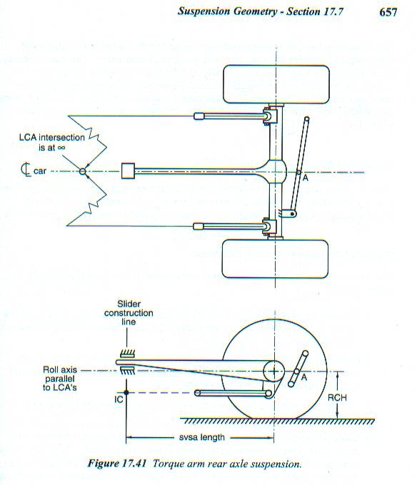
As far as side view is concerned, the IC is a combination of the TA and LCA inclinations and the TA length. Drop a line that's perpendicular to the TA (as defined by the axle shaft center and the TA's chassis end pivot) from the TA's chassis end pivot point. Where the line through the LCA pivots intersects that perpendicular line is your SVIC. The Millikens' "Race Car Vehicle Dynamics" has a good picture (Fig. 17.41) and description.

Norm
 
Thanks Norm.

That is what all the drawings that I have seen,say.
It seems that the front mount of the TA is the instant center unless the two lines cross behind the TA front mounting point.
Is this correct?

How then do the LCA's work with the torque arm to provide forward bite? How do you keep the nose on the ground and provide max bite? How do the angles work together to give you weight transfer? How to get the whole car to raise and provide bite instead of squating in the rear?

I can get the rear to seperate but the front wheels are 6' in the air,I am trying to eleminate the wheelstands.

What about the height of the front TA mounting point and the problem I ran into with the wheel standing after raising it 1-1/2"
 
The SVIC can be at a "real" TA's front mount, but that would only be by coincidence. That the TA's front mount must in some manner accommodate plunge by the TA means that the IC is normally elsewhere.

Umm, perhaps it's time to ask just what kind of car/rear suspension is involved, just to make certain that we're thinking of the same thing. F-bodies (and I think the various Vega/Monza platform variations) used a true torque arm, but what was termed a TA in the GNX (and in Kirban's early advertising copy for their identical product) is something else. That one is also capable of resisting fore/aft forces (and had better line up pretty closely with the front LCA pivots as seen in side view for anything resembling reasonable street operation). In the GNX arrangement, the SVIC is always at the chassis pivot of the traction bar/single ladder bar component that attaches off a reinforced diff cover, and this may be introducing some confusion.

With a torque arm, what you do know is that the TA's front mount ideally sees only a force that's perpendicular to the TA (assuming either frictionless sliding within a bushing or a double rod-ended vertical link arrangement). That force points to the IC, and you should be looking at the physical length of the TA and the virtual length along that force line as making up an L-shaped arm. You also know that the LCA forces point straight along the LCAs and must also be aimed at the IC. That's what defines the arc through which the axle moves, even though the vertical force can only be applied at the TA bushing. The anti-squat property of this arrangement is mostly a function of the LCA inclination and TA length, with TA inclination having relatively little effect.

A GNX style piece is different. In its OE configuration it is much shorter relative to the wheelbase than the F-body TA is to its. The arc in side view that the axle must follow can be completely defined by it alone. That leaves the LCAs responsible for axle end fore/aft location and (some of) the fore/aft force only. Raising the pivot of the GNX device is going to have a far greater effect on IC position and anti-squat than raising a TA bushing end. If its pivot wanders very far from the LCA pivots the rear suspension will tend to bind up, as the LCAs and the traction arm will start having different ideas about the arc that the axle should be following. One conceivable end result would be for some rear end lift to occur (assuming >100% anti-squat), followed by whatever compliance remains in the suspension bushings to be used up resulting in an increased tendency to lift the front. It's your mention of the sensitivity of the suspension to only 1.5" pivot relocation that has focussed my attention in this direction. If I'm off-base here, just ignore it.

Norm


Thanks Norm

This is a '94 Camaro with 687FWHP,11" slicks. The TA has a heim end in the front with a strap on each side to attatch it to the frame(body)where there is another heim ball. The rear of the TA is mounted solid ,with an adaptor bracket.When first installed it appeared to run about the same angle as the factory one that mounted to the trans.This one is shorter by 8-10 inches and mounts where the tunnel brace was. The LCA's are 1" chrome moly with heim end's and have about a 3* up angle from rear to front.
I changed nothing but raising the front TA mounting point and went up 1.5 inches(made new strap's) and reset the pinion angle(electronic angle finder) back to -2* where it always was and it stood up on it's bumper. I have seen several car's(Cameraro's and Trans Am Pontiac's--same chassis) do this when they raise the front mount but I didn't go as high as them and thought I was safe. "NOT"
Came damn near to turning over backwards before I got out of it, then the down crash tore up a bunch of stuff under the car.
I want to understand why this happened so I don't "adjust" myself into the same situation again.
I understand (I think) about the to lines of the TA and LCA crossing at the CG and that the TA is the lift point but I am missing something big time.
 
I still don't understand what raising and lowering the front mount on the TA does and why it effected my car with a wheelstand? It has to have an effect.

Larry
 
If the link is not perpendicular to the axis of the TA, or does not remain so as you make your run (it can't, actually, with any sane link length), the construction for IC will be somewhat different from the normal construction depicted for a TA that slides within a bushing of fixed position. I suspect that the IC for a TA that uses a link has to be at the intersection of the LCA and the link axes, and that an IC so defined would migrate rearward as the rear lifts (separates). That would appear to make link inclination the critical tuning parameter rather than TA inclination.

It's only speculation on my part, but your IC may have already been slightly rearward of the "sliding bushing" construction point, and would have moved further aft as a consequence of the shorter link if the same chassis pickup point for it was used. If that's the case, the AS% could also increase rather more rapidly as the rear rises than it does for a "normal" bushed TA. So I'd add link length to the list of things more critical than TA inclination in this arrangement, at least dynamically.

Norm
 
Been fighting a hurricane and had no time for reply.

Thanks Norm.


The line from LCA's and TA were almost parrellel and didn't have any crossing point before I raised the mounting point..When I raised the front link mounting point,that seperated the two lines more and they could not have ever crossed even a mile in front of the car.
I understand the crossing point if it is behind the TA mounting link's,but what about if they never cross?
If the crossing point is ahead of the mounting links is this the same as the crossing behind the links except the IC moved forward?

Larry
 
I hope everyone's OK in your neck of the woods. Kind of lame, but I don't think I can even begin to comprehend the magnitude of the mess.

It's not the intersection of the TA's axis itself and the LCA axis that you're looking for, but the intersection of the LCA axis and the force line which is along the axis of your TA's chassis-end link. Under load, which probably differs from its static orientation.

I'll take some responsibiity here, as I had initially described an OE configuration where the [force] "line perpendicular to the TA" is directly tied to the TA's inclination. That's where the TA with a link differs, as the link can be at any angle with respect to the TA.

Norm
 
Thanks Norm

We did not get a great amount of damage here but it will take several years to correct the damage done east of here.

I think I've got the IC with parallel lines.

With the links setting dead 90* to the ground and chassis,how did raising the front of the TA put the car on the bumper? I don't understand how that would happen by raising it 1-1/2" and the lines still will not intersect and the IC didn't change(mounting point).
There is something going on concerning the height of the TA mounting point in relation to the CG that I really don't understand because the IC was not changed(heim end was extended and new links were 90* to the chassis and ground) if measured by the perpendicular line drawn between TA front mounting point and the line of the LCA's. Attitude of the car is 1/2" rake measured at rocker panel front and rear.(down in front)The LCA's and ride height,springs,gear,pinion angle(set back to 2*) and shocks were not touched.Launch RPM's were the same(electronic controled),tire pressure was the same and we had run this track many times and were fimular with the starting line.

The side view anti squat line don't work 'cause I was above that line and should not have stood it up.That is if I understand the AS line correctly.

In other words I would like to know what raising it,and lowering it and compared to what referance point does to the weight transfer of the car. I've got a real good idea what raising it does but don't know why or if I had gone 1/2" or 3" what the effect would have been.
 
It doesn't sound to me like you have 'got it' yet. If I am wrong than I apologize.

For me the easiest way to wrap my brain around a suspension like yours is to think of it as a 3-link. In essence the TA is just a 'very long strange shaped link bracket' just like the short brackets that connect the axle tube to the lower control arms. Just think of the torque arm as a part of the rear axle housing and not as a link or control arm. The real 3rd link would be the one going from the chassis end of the TA to the chassis (short and almost vertical).

If you are using a suspension software then start with a template for a 3-link + Panhard bar suspension and ignore the TA and use the short vertical link instead.

This is a link to the figure that Norm was talking about
Ta.jpg

Antisquat.JPG

(I didn't scan those and take no responsibility for the copyright)
 
I got all of it(I think) I have been trying to treat it like a 4 link but nobody has said what raising the TA does if your lines are parallel.Or lowering it and the LCA's to make parallel lines .Where is the IC and using what to reference the IC.
 
Status
Not open for further replies.
Back
Top