Daniel Ursache
Mechanical
Hello gentlemen,
Let's consider an independent front suspension (e.g. double wishbone / SLA). Everywhere on Internet is described the way you can easily find out the location of IC and RC points.
In all explanations and in all pictures I saw only that unique case where the mounting points of Lower Control Arm / Upper Control Arm to the chassis both are on the same plane.
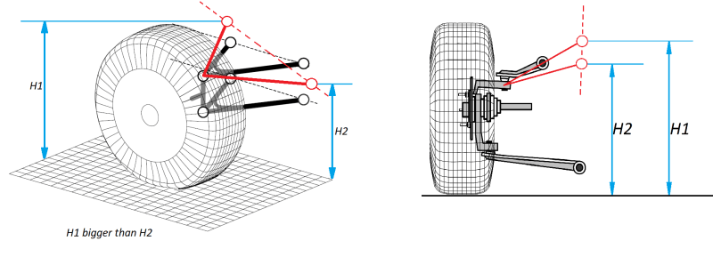
Here it comes my question, how do I supposed to determin the IC and RC points for that case where my mounting LCA / UCA to the chassis are not on the same plane ?
Please check the imagines below for more detailing. Thank you very much for your time.
Best regards,
Daniel
Let's consider an independent front suspension (e.g. double wishbone / SLA). Everywhere on Internet is described the way you can easily find out the location of IC and RC points.
In all explanations and in all pictures I saw only that unique case where the mounting points of Lower Control Arm / Upper Control Arm to the chassis both are on the same plane.
Here it comes my question, how do I supposed to determin the IC and RC points for that case where my mounting LCA / UCA to the chassis are not on the same plane ?
Please check the imagines below for more detailing. Thank you very much for your time.
Best regards,
Daniel