Continue to Site

Eng-Tips is the largest engineering community on the Internet

Intelligent Work Forums for Engineering Professionals

  • Congratulations SDETERS on being selected by the Eng-Tips community for having the most helpful posts in the forums last week. Way to Go!

Ideal Flange Constraints/Neglect Flange Constraints 1

Status
Not open for further replies.

Doodler3D

Mechanical
Jan 20, 2020
188
Greetings Experts.

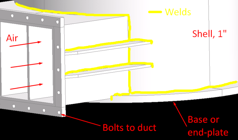
I am a new FEA engineer and have been tasked with a simple FEA analysis of a pressure containment vessel at 120 psi. The vessel has passed the EN 13445 standard but also needs ASME certification. My senior colleague has completed the ASME VIII Sec 1 calcs to approve the design. However, he's asked me to have a go at FEA and treat this task as if there was no ASME report to play with.

Material of Construction: SA240 ASME Stainless Steel 304L

Outlet flange thickness: 3/4"
Base thickness: 1"
Outlet duct plate thickness: 3/8"
Shell thickness: 1"
Rib thickness: 3/8"
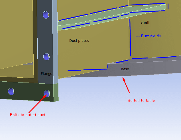
Screenshot_16_fplwgy.png


Questions:

1. How should the flange be appropriately constrained?
If I constrain the bolt holes or flange face, the stresses will increase. If the flange is left unconstrained, I may have unnecessary deflections.

2. Should I model welds?
Since the welds are all butt welds, if I treat the structure as a bonded continuum, would that drastically increase stiffness. I've read that good butt welds and penetration welds have equivalent stiffness as the parent material, including the HAZ.

3. Sub-modelling welds and ribs
How relevant it is to model welds on ribs as I expect stress concentrations to occur at the base of the ribs

4. Is pressure compensation important since I'm leaving the exit open? If not, do I need to cover it with a plate of relevant thickness?

Thank you.
 
Replies continue below

Recommended for you

I have just about no idea how to read your pic !?

I get where you're coming from, but I would rather you go to your mentor with thee questions.

You are asking good questions, and show some good sense about the issues.
Your flange question … yes, two extremes … how can you get it "right" ? (this is what you mentor will ask, and if your answer is "those guys on Eng-Tips told me …", well you know where the rest of that conversation is going.
Same with your weld question … two extremes, how can you get something closer to reality ?
3rd question … do or do not … see their impact on the structure (probably insignificant as you expect … how can you verify ?
4th question … sorry, but WTF !? how can you pressurise an open vessel ? sure you can apply pressure to the remaining 5 faces … is that real ? Is this just the end of a long pressure vessel or is there an endplate (closing the volume) nearby ? what is "pressure compensation" ?

another day in paradise, or is paradise one day closer ?
 
Thank you, rb1957.

I hope this pic helps
Screenshot_17_pfiir3.png


My mentor is not a mentor, but an elderly person who has no FEA experience. Also, the firm is relatively small and I have just taken a basic FEA course to begin with.

I believe my answers lie in my own engineering judgement and further reading, else garbage in = garbage out.

A1. Since the long ducts are suspended from ceiling hooks, flanges for the inlet and outlet need not be rigidly constrained.

A2. Since the welds are not expected to fail, treating the welds as a continuum would suffice.

A3. I can sub-model the components, just to note areas of high stress concentrations

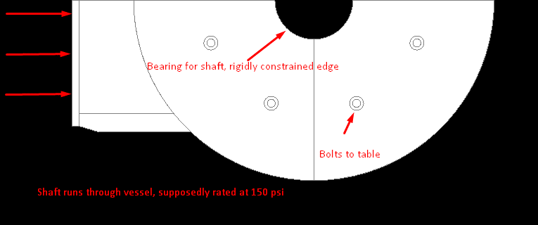
A4. I may have misunderstood pressure compensation, if it exists (using constrained bodies as a boundary condition when the vessel has openings). I heard the term in this video (@ 20:00 mins). In my case - since the vessel has a shaft that runs through its center, the bearing areas of the shaft ends have been constrained rigidly. (bottom view below)
Screenshot_18_mponpy.png


Thank you, again.
 
@rb1957,

Maybe pressure compensation refers to reaction loads?
 
Dear Daru,
Is very easy, you have two options:
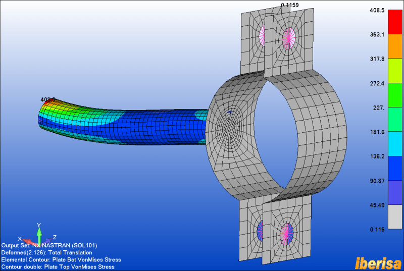
1.- Create the MIDSURFACE of the flange with holes to mesh with 2-D Shell CQUAD4 elements and define an spider of rigid RBE2 elements and in the center node prescribe a pin constraint (TX=TY=TZ=0) simulating a pin joint where the bolt is located. This way you can compute the reaction forces in the pin constraints, and use the reaction forces values to dimension bolts.

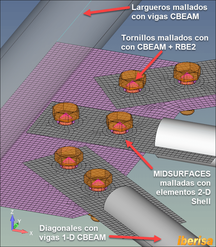
2.- Include in the Finite element model also a portion of the outlet duct (constraint the end duct), and discretize both flanges with two midsurfaces with holes including the bolts: mesh the bolts with CBEAM elements with spiders RBE2 elements at both ends, and define contact surface-to-surface no-penetration between both flanges.

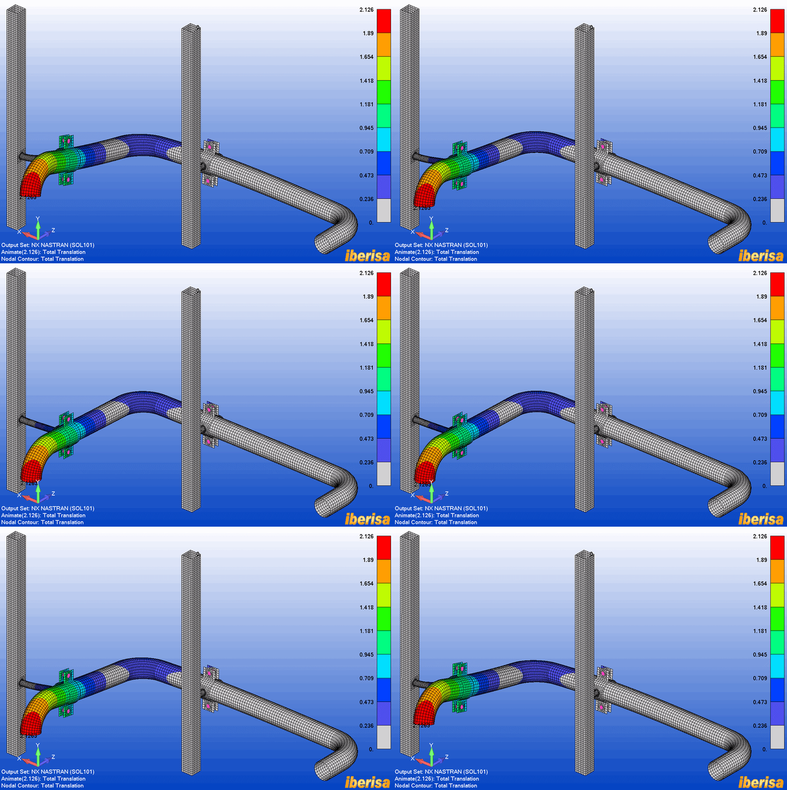
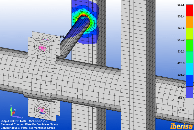
Some examples here of flanges meshed with 2-D Shell CQUAD4 elements and bolts with CBEAM elements:

CONNECTION_URES_ANIMATED_gp7lkt.gif


CONNECTION1_ifr0lq.png


CONNECTION1_brida_tjrigt.png


I hope the above examples show you how to mesh flanges.
Also in this video you have the way how to mesh bolts between two plates:


celosia-mallado-metodo-local_cetnr4.png


Best regards,
Blas.

~~~~~~~~~~~~~~~~~~~~~~
Blas Molero Hidalgo
Ingeniero Industrial
Director

IBERISA
48004 BILBAO (SPAIN)
WEB: Blog de FEMAP & NX Nastran:
 
Thank you, Blas for the elaborate explanation.
 
Status
Not open for further replies.

Part and Inventory Search

Sponsor