Continue to Site

Eng-Tips is the largest engineering community on the Internet

Intelligent Work Forums for Engineering Professionals

  • Congratulations Toost on being selected by the Eng-Tips community for having the most helpful posts in the forums last week. Way to Go!

Idealizing a 2D Bracket Assembly 2

Status
Not open for further replies.

Doodler3D

Mechanical
Jan 20, 2020
188
Hi,

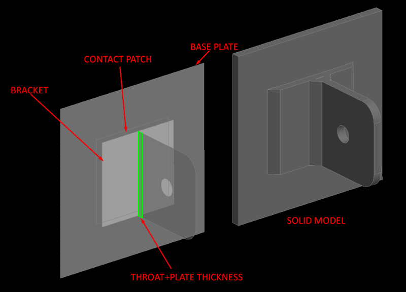
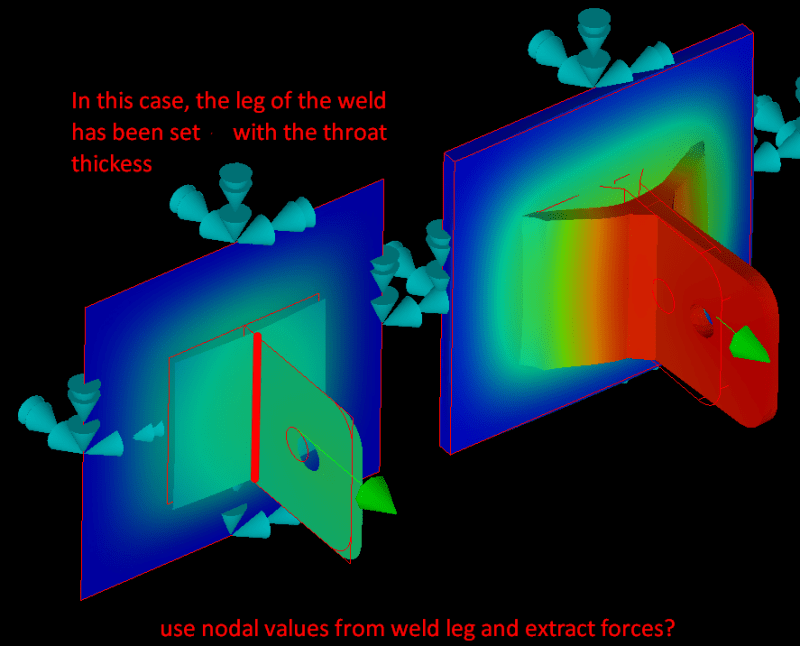
FEA rookie here. I am trying to simplify a 3D bracket welded to a curved surface, using shell elements. Hand calcs average weld stress is 160 psi. The idea is to transfer the load and not worry too much about the weld. Thicknesses are 0.25" and material is A36 plate. 100 lbf force acts from the hole center and the base shell is constrained.

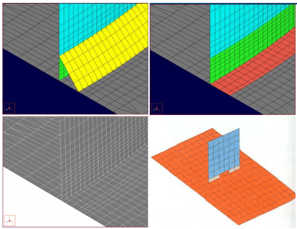
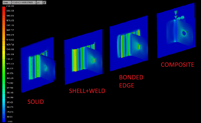
Based on the image attached (left to right):

1. The full 3D mesh has an average weld normal stress of around 170 psi (Solid 3D mesh)

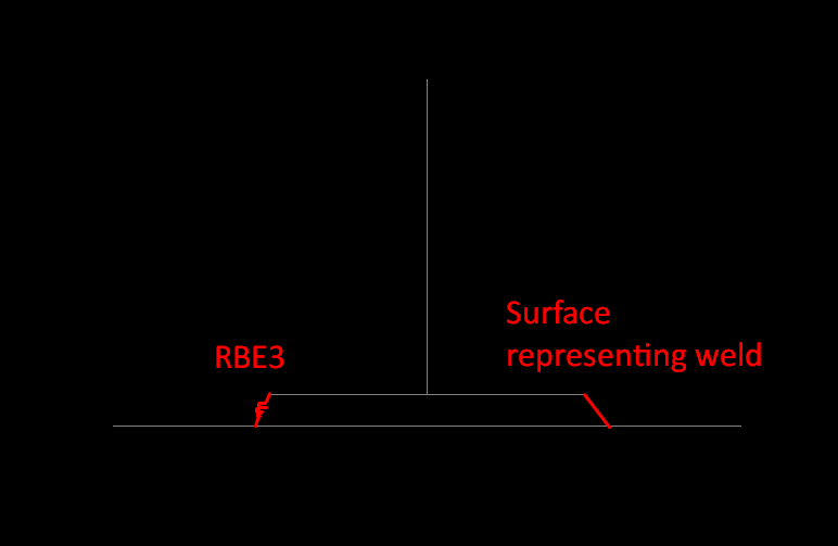
2. The model includes only the surface representation of the weld (Shell mesh)

3. The model has the edge directly bonded to the curved surface and the weld is disregarded (Shell mesh)

4. The surfaces of the welded bracket and the curved shell are combined, i.e. 0.25" + 0.25" (Shell mesh)

Question:

To correctly interpret my results, is St. Venant's principle sufficient to assume that the idealization is correct?

PLATE_BRACKET_mtnfta.png


Thank you.
 
Replies continue below

Recommended for you

You don't tell us how the base shell is constrained, so its hard to say. Easiest way to see if St Venant would approve of your work is to double the size of the base shell. If the answer doesnt change , or changes only a little, then he's happy. If there is significant change, then double it again.

A couple of comments. Sounds like you made the bracket part that is parallel to the base double thick to account for the thickness of the two plates. That over-stiffens the plate. Deflection in a shell is proportional to 1/t^3. So, 1/0.5^3 = 8, 2(1/.25^3)=32, so jointing the plates cuts the deflection by 75% resulting in a 4X increase in stiffness. Might not hurt you here, but Ive seen people do that and get bad results. Second, applying constraints and bonding an edge can give different results, depending on how you do it. Remember that solids are 3 DOF elements whereas shells are 6 DOF. Lastly, I dont think its a good idea to discretely model the weld. Just bond it, then take the joint reactions and apply them to the weld allowables. See Design of Welded Structures by Blodgett or Mechanical Engineering Design by Shigley.


Rick Fischer
Principal Engineer
Argonne National Laboratory
 
Thank you Rick,

I was trying to implement some idealizations from literature, where the base plate is fixed at its edges.

SHELL_WELDS_zrrf7s.png


I just got Omer Blodgett's book last week. Your saying that I take the bracket as is, bond it directly to the contact patch, extract the nodal values at the weld toe from the results and use the equations from the book to check the safety factor of the welds? Wouldn't that over-stiffen the model? In reality, pulling at the eye of hole would lead to a deformation that would bend the bracket into an arch? I also found some conflicting posts where the base of the weld is modeled as throat+plate thickness (2nd pic) and in some cases just that throat, since that is the least c/s of the weld (3rd pic).

I hope these pics are clearer.

Screenshot_237_on6weu.png


Screenshot_240_rxno8k.png
 
@Doodle. Rick is absolutely right, weld calculations are best done by hand, with by far the most used and revered method being that found in Blodgett's book. For a model this simple you can ignore the welds. Just merge the nodes and calculate the weld strength and weld requirement by hand. If you want to also model the weld in FEA and see how close you get to your hand results, go for it, it's great for learning, but do not count on FEA to design your welds.

“The most successful people in life are the ones who ask questions. They’re always learning. They’re always growing. They’re always pushing.” Robert Kiyosaki
 
Megastructures, Rick. I appreciate your inputs.

I have a few old FEA reports where the consultant used ASME elastic plastic analysis to review the strain in welds under pressure based on the API 579-1/ASME FFS-1. In that case, since the equipment has already been designed and installed on field, would it be wrong to use FEA with the code to validate remaining life and safety factors of welds? Accordingly, is my attempt to model idealized welds appropriate?


Megastructures, since the base plate and bracket midsurfaces are 1/4" apart, would that mean that the welded edge of the bracket is to be merged directly with the base plate? Is that done by using a surface that would represent the original weld or is it appropriate to use rigid elements?
Screenshot_242_xaxbnp.png
 
You are at a point where Design by Rule and Design by Analysis intersect. Blodgett is design by rule. If your weld looks like this, calculate stress like that, and compare it to this allowable. The calculation is simplified and the allowable is knocked way down to account for all the stuff you cant control or include in hand calculations. Very conservative, but it works. Its based on lots of testing and lots of experience. FEA is of course design by analysis. You can build a detailed model of complex geometry and generate stresses up the kazoo, but what do you compare them too? If you use the allowable from above, it will likely fail. look at your model. Its shell elements at a right angle. The ends are singularities, so you'll always get a very high stress that always says failure. And you haven't accounted for poor weld penetration, shrinkage, slag inclusions, residual stress from uneven heating and cooling, etc, etc. If you start with the yield and tensile strength of your filler, do you compare your stresses to that, or do you knock down the strengths? How much? This is all included in the design by rule method. There is lots of chicken factor built in. The weld stress in design by rule isn't an actual stress, its a stress convention. Its a measure of how critically the weld is loaded. But FEA gives you a real stress that is closer to reality, sort of, maybe, depending on how you model and with how much detail. In general, if you want to use FEA, it is best to get force and moment reactions from your FE solution, then use that with Blodgett.

Regarding your question about your existing equipment, do the analysis the way the code says, follow their procedure, use their material data, and you should be OK. I cringe when you say factor of safety regarding the BPVC. Haven't done the elasto plastic weld strain analysis you're talking about, but generally, if the code says you pass, and you did the calculation right, you're good. There is a factor of safety built in that is appropriate to the analysis method and material properties they have specified. If you start trying to pile more chicken factor on top of that, things could get expensive real quick. My experience is that people not familiar with the code dont understand that, and always want more. I use the term "analysis margin" to describe something that is better than the code requires, but to suggest that a design that just meets the code has a factor of safety of 1 is wrong. The analysis margin is 1. The factor of safety is appropriately larger than 1.

Rick Fischer
Principal Engineer
Argonne National Laboratory
 
Rick,

All our equipment is 7-10 gauge, rectangular C/S vessels, and in most cases design by Rule does not work. I've only recently enrolled in NAFEMs code courses, but there is a ton of conflicting information as I try and digest the concepts. What I have seen so far, is that organization/consultants have their own weld benchmarks typically based off a hot-spot method like those described in ASME papers by Dr Dong, D. Osage etc. And yes, my ASME jargon is still unrefined, I should refrain from using 'factor of safety' henceforth.

From this post I've learnt:

Hand calcs: Blodgett/Shigley

ASME CODE DBA:
Fatigue -> Weld hotspot based analysis from a relevant paper/application and compare the allowable stresses to meet the code requirements.

Elastic-plastic analysis -> Check the plastic/limiting triaxial strain.

Edit:

OR pull nodal forces and moments and use Blogdett, as suggested.

Surely I'm mixed up here.

Thank you.


If you're analyzing something simple, like your bracket, hand calcs with Blodgett are fine. If the geometry, loads and boundary conditions are complex and joint reactions are not easy to determine, pull the nodal forces and reactions from FEA and use them with Blodgett. But if you are doing work governed by a code, follow the code.

A couple of references you might find useful:

"Determination of Weld Loads and Throat Requirements Using Finite Element Analysis with Shell Element Models - A Comparison with Classical Analysis" by M. A. Weaver.

AISC 21 Welded Connections, A Primer for Engineers.

Recommendations for Fatigue Design of Welded Joints and Components by A. Hobbacher, International Institute of Welding.

Rick Fischer
Principal Engineer
Argonne National Laboratory
 
Thank you for the recommendations, Rick.

I just created Weaver's model and now things are making sense to me. I have a long way to go before calling myself an analyst.
 
Status
Not open for further replies.

Part and Inventory Search

Sponsor