Eng-Tips is the largest engineering community on the Internet

Intelligent Work Forums for Engineering Professionals

Ideas about the noise source causing this.

Status
Not open for further replies.

itsmoked

Electrical
Feb 18, 2005
19,114
0
0
US
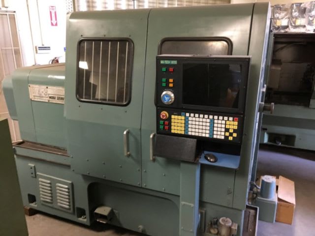
I have a big Yaskawa drive controlling the spindle on a fairly large CNC Mori Seiki lathe.

Mori_Seiki_Lathe_z15cix.jpg


The spindle speed wanders all over the place. Set it to 1,000RPM and you can watch it roam down to 500 and up to 1,700rpm. Set it to 1,500rpm and watch it roam up to 3,500rpm and down to 1,000. Setting it to 2,000rpm you can watch in horror as it heads for 6,500rpm, pulling the plug as you think about a foot-in-diameter chuck spinning that fast. The changes are random and almost constant with several changes a second occurring.

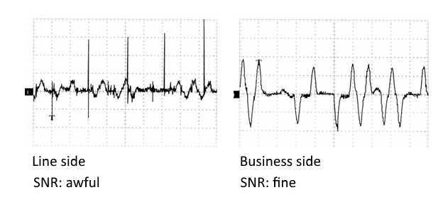
The spindle speed is fed back to the drive via a resolver. The resolver is the classic three winding transformer with two secondary windings oriented 90° apart. A driving rotating primary coil is fed an 18kHz sine-wave by the drive's front end. The envelopes of the receiving secondaries are subsequently compared to provide an accurate realtime rotor position/speed.

Speed problem? So I head to the resolver and stick my scope on it and this is what I see on the driving coil.

20190212_171554_uzg86t.jpg


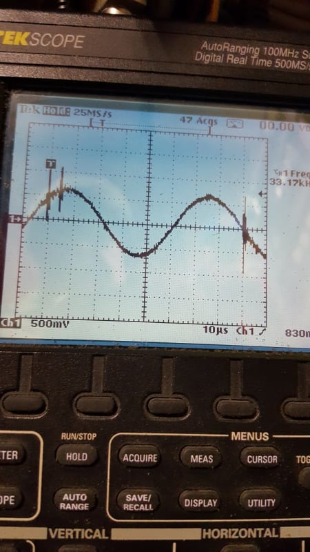
The spikes are pretty accurately reflected in the two secondary coil outputs. The motor hunting can be seen and felt to be associated with these interference spikes. My scope set in "tell me the frequency" measurement shows 18kHz with subsequent measurements showing up as a couple thousand Hertz and 130kHz etc etc so it's not a surprise the drive is misreading this too and sending the spindle off into the weeds. The drive's PIDs these wrong speeds and before getting anywhere diverts off to the latest wrong speed, this is happening several times a second.

I'm trying to figure out if these spikes are a failing part in the drive's resolver excitation circuitry, perhaps only a filter component failure and motor drive power is appearing on the encoder drive? Or, maybe the motor has lost ground continuity and high freq current is riding back on the resolver wiring. Seems odd it would be bigger on the resolver drive channel than the receive channels if that was it.

Got any ideas what causes this particular type of interference?


Keith Cress
kcress -
 
Replies continue below

Recommended for you

Did it happen "from birth" or has it started suddenly?
The encoder is obviously a sine/cos "Inductosyn" type. Do you have the same interference on the other channel?

Gunnar Englund
--------------------------------------
Half full - Half empty? I don't mind. It's what in it that counts.
 
Hi Gunnar; The lathe hadn't been used for a month or so and was set up to do production as it's used for a specific product year-in-and-out. This time when started up this was happening.

Yes, it is a sine/cosine type deallywhopper. The driving channel has it large and the two driven channels (with a common point) both have it but with reduced amplitude, reduced the same as their normal received outputs.

Keith Cress
kcress -
 
I guess that you already checked the screen grounds, the bonding and such things. Even if a grounding/bonding looks OK - it may be worth-while to check the connections. Especially if there are aluminum alloys involved. Known to develop insulating oxides over time. Unscrew all and clean. Add some good contact spray (don't recommend that otherwise). Check cable shoes and their pressing. Replace if it doesn't look 100% perfect. Tighten everything a little bit below breaking.
That is how I would start the job. Adding more screening and ferrites does not seem to be such a good idea. Even if the result may be marginally better - it will come back and bite you.


Gunnar Englund
--------------------------------------
Half full - Half empty? I don't mind. It's what in it that counts.
 
Also, if the encoder housing is Al alloy. The grounding to the machine/or motor is good to check. Unscrew fixing bolts add some contact oil and re-tighten. Check between every single "attac". If something works, it is good to know what it was.

Gunnar Englund
--------------------------------------
Half full - Half empty? I don't mind. It's what in it that counts.
 
Oh, no! That pic says it all.

Try to keep your mouth closed. Especially when among people. I know it is a problem without the NV. And probably impossible now. Get better. Soon!

Gunnar Englund
--------------------------------------
Half full - Half empty? I don't mind. It's what in it that counts.
 
Hiya Keith

Dumb question guy here, hope you're feeling better. You have ~1.2V pp and I know that is acceptable for a resolver I think. My question is with that small amount of voltage are you getting
enough current to drive the resolver?

Chuck
 
Good point Chuck. Now that I think about it that picture above is the resolver output because I remember having to set the scope to a couple of volts per scale to see the excitation but you've still got a point, a volt isn't much in that noisy system.

And thanks, I'm improving quickly as I had actual food (not much) for dinner last night. :)

Keith Cress
kcress -
 
If that is the output, you do have a problem. There shall not be any spikes on a resolver output. In: yeas. Out: No.
CMRR and isolation takes care of that.

Floatng measurement on coil outputs? Or did you put the ground lead to machine metal?


Gunnar Englund
--------------------------------------
Half full - Half empty? I don't mind. It's what in it that counts.
 
Gunnar that is a completely isolated scope where there is no ground - period. That was at the terminal block where the cable from the resolver translates to a D-ish connector plugged into the drive unit. No grounds anywhere that I was aware of or on the actual schematic. Except for the cable shield.

resolver_viro7r.png


The resolver schematic looked essentially like this except only five wires come out as S1 ans S2 are combined internally.

In my absence he bought another used resolver and tried the stator only since the rotor is a nasty gear like structure pressed on the motor shaft - no wires or moving parts - and while I have not been back yet he sez it still has the problem and that the motor hunting around still occurs and he's even seen the motor going backwards in its hunting while never commanding reverse.

Keith Cress
kcress -
 
Yes, I know them well. Done them soo many times from inductosyns to 400 Hz in planes and Fanuc/Siemens CNC:s in-between. And I have had a THS 720, too. Loved it.

I used "ground" for the reference potential when measuring that resolver output. If the reference is connected anywhere else than to the resolver winding S* then you get the signal, carrier plus modulation PLUS interference. That is why I asked. But if the measurements were taken between S1/S2 or S3/S4, then there shouldn't be much interference at all.

Pic shows a similar situation (no resolver, this was communication in subway but the principle still holds. If interference can be seen on business side, it is mostly due to either dubious bonding or measurements taken with wrong reference. I still think that you have a problem with corroded ground path. As I said in my first post. The fact that it occurred after weeks of inactivity (things keep in shape when you move/vibrate them and also if some heat is allowed to keep moist away). Just sitting there for weeks (in salty mists from the Pacific) often leads to exactly the problem you describe. The field support at Mori Seiki or Yaskawa should know about that.
image_qmv12k.png


Gunnar Englund
--------------------------------------
Half full - Half empty? I don't mind. It's what in it that counts.
 
Thanks for the pics. I too feel it is the grounding and your inactivity scenario fits to a tee the place is cold concrete and a whole 5 blocks from the ocean..

I wish I could get over there but I need to be confident I won't pass him the plague (still shaky).


Keith Cress
kcress -
 
Status
Not open for further replies.
Back
Top