Eng-Tips is the largest engineering community on the Internet

Intelligent Work Forums for Engineering Professionals

Identifying Windings on 12 Lead generator 1

Status
Not open for further replies.

drlnguptx

Industrial
Nov 18, 2015
8
0
0
US
thread238-314092

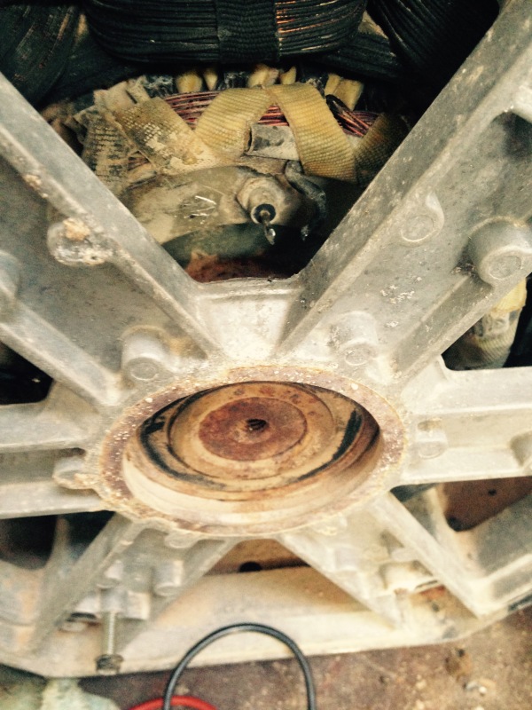
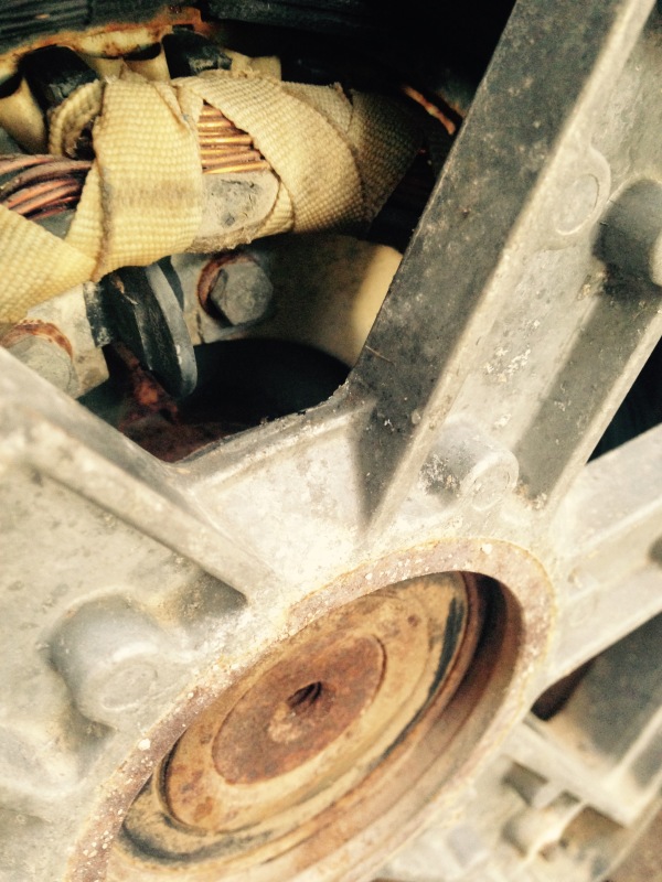
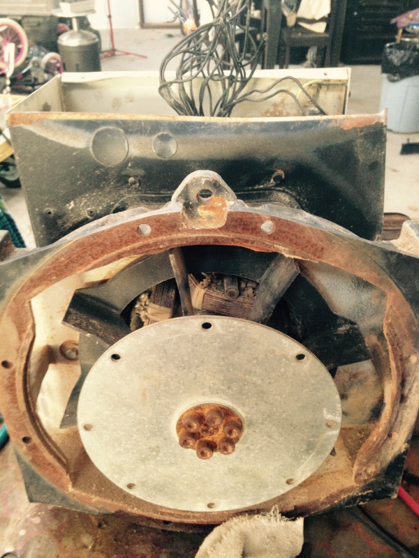
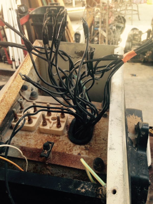
Great post above~! I am in the exact situation...I've got a genset here that someone has cut all the output wiring. I've been able to identify the coils and yes, I did have to disconnect the diodes on the rear to identify the remaining 3.
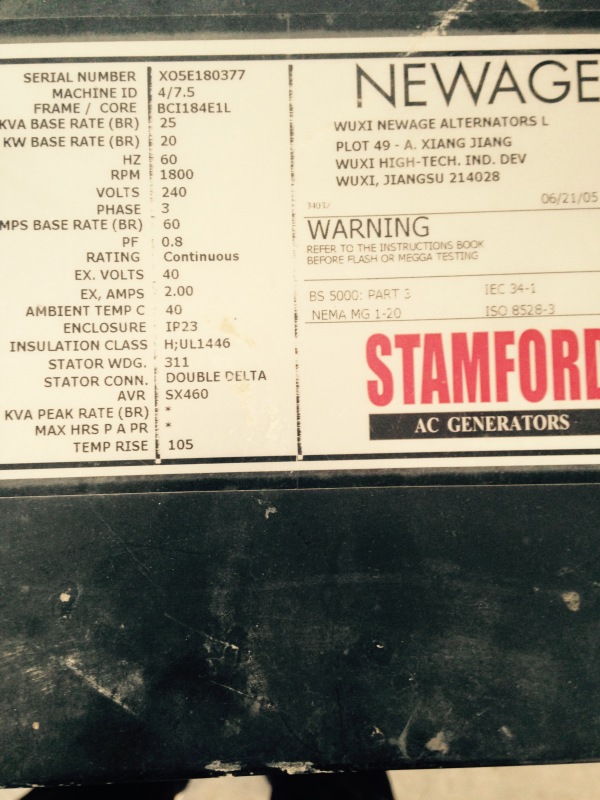
Forgive my ignorance here, but it was stated to excite the gen with AC. The Gen I am working on does not have any AC plugs attached...how would I go about exciting it??

Thank you all in advance!
 
Replies continue below

Recommended for you

Obtaining some wire, suitable termination devices/materials for same (wire nuts, split bolts, tape etc.) and an adjustable voltage, preferably current limited source of AC would be a good start.
 
The referenced post indicates that you should excite (apply voltage to) the machine's field. Do any of the external leads go to the field?
 
There are the two wires left that would originally go to an avr....are those the wires that I shall apply the rheostat to?
I thought those were DC only...
 
Those wires probably go to a small stator winding near the back end of the shaft. There will be a rotor stator riding on the shaft, inside that stator. That is the brushless exciter. From the rotor windings 3 wires should travel down the shaft to the diode plate. The six diodes on the diode plate convert the AC output of the brushless exciter to DC for the main field. Two wires run from the diode plate to the main field. Disconnect these two wires and apply DC to the main field with a pair of long flexible wires. You can turn the shaft a couple of turns manually before you have to either reverse the direction or unwind the wires. I suggest starting with 12 to 24 Volts AC. Increase the voltage if you need to to get good readings. Given the high impedance of the field winding at 60 Hz the field is probably safe up to 120 VAC applied. However, with 120 VAC on the main field, the output voltage of the windings may be too high for safety. Best to start with a lower voltage.

Bill
--------------------
"Why not the best?"
Jimmy Carter
 
Apparently, everything I thought I knew, or have known does not apply to this particular project...I digress...I figured defining these wires is beyond my immediate expertise so I sought a repair company locally to define the wiring. Unfortunately, that has too, failed...so I am back to solving this myself...Please instruct my ignorance....


I have 26 wires that come out of this 3 phase (25 kw) generator. I know power output by the markings.
2 of them have electrical clips on them which I assume go to an avr. That leaves me with 24 wires.
What I've done thus far.
With an ohm meter, I've checked for continuity on all wires. 18 of these wires pair continuity which I have separated.(9 pair) I've got 6 left that I assumed went to the diodes on the plate. I disconnected the diodes and there is no continuity with anything having to do with the remaining 6 nor any pair I've found.
I've researched the crap out of how generators work to how they are wired and still find myself...elementary...logic tells me that I have 24 wires....math tells me that I should be able to divide by 2 and come up with 12 pair, divide again by 2 and finally sum 6 leads... in which, I could excite and find the phases. But as mentioned above, 6 wires remaining and no continuity or similarity exists with the tests I've performed between the 9 pair and the 6 nor the 6 themselves...

Am I doing something wrong? Is the generator head broken? The only history I have behind this unit is that I was told a diode was bad and a little diagnosing was needed to replace it.
I rarely give up anything to the mouth of a dumpster!! What do I do?

Thank you for any help!!

 
Mike,


Thank you for the information...

I've got 24 wires coming out of the head that are not identified. How do I narrow those 24 to 6 pair to start testing phases with a battery?
18 out of the 24 wires ohm out to each other. That gives me 9 pair, if you will. However, there are still 6 additional wires left...Could this be a "dual wound" generator? Could the remaining go to a switch for polarity..ie...uvw, wvu?

Thank you

Chris
 
Sounds like you have a 12 lead machine with 2 wires per lead. That makes it even harder. A motor shop affiliated with EASA should have access to an old procedure they had that used a surge tester to identify leads. That reference guide is still in their library but you need to be a member service company to access it. I used to have a copy but can't find it anywhere, and it takes someone who has experience using a surge tester to get it right.

One thing you can try is to seperate all the leads, if this is a 12 lead two in hand (old terminology for two wires per lead) then using an ohmmeter you should find 4 of the wires with continuity. Once you have the six sets of windings grouped, if you have access to a Wheatstone bridge or a DLRO you should be able to determine which of the four wires are at which end of the winding. Then once you have them grouped into the 12 leads you can use the procedure and identify them properly. It helps if you assign temporary numbers to all of the wires and do up a drawings to keep track. I attached an old sample.

Last time I did this was several years ago with a 12 lead three in hand (36 total wires coming out)machine, it took about 7 hours and I had done this type of procedure before. You need to be methodical and patient, but you should be able to figure it out. Otherwise you may need to take it to a motor shop and they might be able to identify the leads after a partial disassembly depending on how the generator is built.

Hope that helps, MikeL.
 
 http://files.engineering.com/getfile.aspx?folder=4f910a12-fdb3-430c-a9f5-b8900b2eb87c&file=12_lead_2_in_hand.pdf
Mike,

First, Thank you so much for your time with this...

Is there any logical explanation as to why 18 ohm out to each other leaving 9 pair? Not knowing the history behind this head, I'd hate to put in the time and effort to try and figure it out if indeed, the unit is broken...

Chris
 
This is a little worrysome for a two in hand set.
OP said:
18 out of the 24 wires ohm out to each other
I am wondering if there was a partial burnout and someone cut the leads short to ensure that repairs would be done (Rewind) before there was an attempt to use the set again.
Does this machine have brushes or does it use a brushless exciter? On a brushless machine the diode plate is on the shaft between the brushless exciter and the revolving field. The wiring to and from the diode plate is along the shaft and is not in the main terminal box.
Does it have a PMG? (Permanent Magnet Generator, a small permanent magnet alternator on the back end of the shaft to supply power to the AVR)

Bill
--------------------
"Why not the best?"
Jimmy Carter
 
Based on the info so far I guess we need to backup a bit,

Are you sure this is a "12 lead machine"? How do you know that?

Do you have nameplate info on this machine?

Can you provide a picture of the 24 wires that are coming out of this machine?

Is this a "standard" type generator, or some type of special purpose machine like a military MEP unit?

It really sounds like you need the services of a competent motor shop with generator experience, can you let us know where you are and maybe someone in the forum has a reputable contact they can point you to?

MikeL.
 
All,

If you think I can get somewhere with this, I will build a small wooden jig to correctly separate each one of the wires in order to keep organization testing the fields. Please see the enclosed photos.
The wires wrapped in orange are the mystery...
Mike, I do know of one more shop that I could take it to. I will call them and see if they can identify...

Thank you!


Diode_plate_nwzinp.jpg


Disc_Cap_diode_plate_exifxw.jpg


Front_purnqz.jpg


Nameplate_ggkwit.jpg


Wires_dsq3as.jpg


Wiring_config_kp8isg.jpg
 
OK, so it's a 12 lead Newage, and 2 in hand by the looks of it.

First thing I'd do is add temporary numbers to all the leads

Next, is to megger test each lead to ground at 500 VDC, at a bare minimum you need to be above 1 meg-ohm, Newage prefers a minimum of 10 meg-ohms.

Next, use a DMM and measure each lead to very other lead, you should end up with 6 groups of 4 leads each that have continuity. If you don't have that grouping based on everything provided you have one or more open windings.

In my experience these chinese Newage tailends were terrible, where I worked at the time, we packaged a number of smaller rental contractor units with these and had a huge failure rate. Open windings were common, but grounded windings were most of the failures. Repair cost exceeded replacement costs and we ended up scrapping all of them in 2006 just before I left the company.

Attached is a Newage Fault Finding Manual you may find helpful.

MikeL.
 
 http://files.engineering.com/getfile.aspx?folder=169b0f37-4e48-407a-9006-aa38ea58764c&file=TD_FAULT_MAN.GB_JULY_2009_GB.pdf
Mike,


Thanks again for the information.

After much research locally, I've been informed that you are exactly correct about the Newage Heads. I was not aware that there is a rewind shop fairly close to my location. After speaking with them, they told me that they could identify each of the coils but wouldn't be able to identify the phases. He also stated that even if I miraculously were able to get the machine to run, he would expect it not to run much longer. They've replaced 'thousands' of these heads with only a few hundred hours on them. He said they were a terrible design made with very low quality materials. He too stated that many of them had open windings. I am now VERY suspicious as to why this head is now laying in my shop. I believe my gamble with $200.00 USD and a bad diode is now down the drain. He said he knows exactly where to find a replacement and will quote in a day or so.

I thank you all very much for all the help with this, but I think I will heed the advice, chalk it up as a loss and move forward with a replacement head. Anyone have any use in Texas for a 200 lb paper weight? I have two of them! lol

Chris
 
Status
Not open for further replies.
Back
Top