Continue to Site

Eng-Tips is the largest engineering community on the Internet

Intelligent Work Forums for Engineering Professionals

  • Congratulations KootK on being selected by the Eng-Tips community for having the most helpful posts in the forums last week. Way to Go!

if surface profile tol in the title block ok? 7

Status
Not open for further replies.

juanMElvl300

Mechanical
May 4, 2022
3
Hi users hope you are all doing good.

I have two simple questions.

1) is it ok to have a profile surface tolerance in a drawing title block? (see the below picture)
2) if so, with it apply to all surfaces for inspection?

I'm used to seeing the old way; this profile tolerance must be new. (to me btw)

something like this was the old tol. block
X.X = ±0.25
X.XX = ±0.12
X.XXX = ±0.06
X.XXXX = SEE DIM TOLERANCE

Screenshot_2022-05-04_140924_ypowek.jpg
 
Replies continue below

Recommended for you

chez311,
Thanks for pointing that out. Option (c) was not there in the 2009 version, it is a new addition in the 2018 version that I missed.
But, wouldn't it be clearer if the note included the words "ALL OVER"?
The text of the standard doesn't seem to impose this, and I personally think it's too bad. I would recommend adding "All OVER" in the note anyway if this is the intent.
Regardless, I will post a clarification in the other thread as well.

J-P, I was about to elaborate on how the "ALL SURFACES" wording or the fact the requirement appears in a general note is insufficient for creation of a pattern, but the above update from chez311 regarding how the rules changed in 2018 indicates that my statement is only valid for drawings based on previous versions of the standard.

 
All is good -- I may have been right on a couple of points, but I got corrected by greenimi on one :)

By the way, this brings up an interesting question: In Fig. 11-18 of 2018, why would they use "2X" when they already have the two leader lines? Might someone argue that there are four surfaces involved?
(I see why they have "2X" in Fig. 11-16, but Fig. 11-18 kind of bothers me.)

John-Paul Belanger
Certified Sr. GD&T Professional
Geometric Learning Systems
 
JP - there is only one guy to answer that question. AFAIK he's the only one responsible for creating all the figure artwork.
 
Belanger,
Two leader lines without the number of places indication is not an official way to specify a pattern. The'09 version of this figure showed that (see below), but it was corrected in the '18 revision.

Screenshot_20220505-203947_Drive_kg8pau.jpg
 
Burunduk -- that's true; thanks. But that opens up several cans of worms.
If they had "2X" but only pointed to one surface, we would know that it's still both surfaces. Then why spill extra ink?
Or... if the two leaders are still needed, why not do 2 leaders for other cases of 2X, such as the small holes in Fig. 7-46?

Just trying to stir the pot a little...

John-Paul Belanger
Certified Sr. GD&T Professional
Geometric Learning Systems
 
J-P,
The idea is that "2X" groups the features into a pattern, and the two leaders make it clear what specific two surfaces are referred to. For a more complex part, it could be an issue.
I don't like the multi-leader practice. It usually looks clumsy, and the leaders get in the way of other stuff that needs to be on the drawing. I usually prefer INDICATED.
 
1.3.42 Pattern
pattern: two or more features or features of size to which a locational geometric tolerance is applied and are grouped by one of the following methods: nX, n COAXIAL HOLES, ALL OVER, A ↔ B, n SURFACES, simultaneous requirements, or INDICATED.

There is no definition or explanation for "locational geometric tolerance."
The term "locational" is not used elsewhere in the Y14.5-2009

On that basis I would suggest that the '2009 version has no traceable requirement for how a pattern is established.

It also excludes plus/minus tolerances on hole patterns.

Agreeing with that observation, the Y14.5 committee; the '2018 version had a massive rewrite to be very specific about what was acceptable. They would not have done so if the '2009 version was adequate.

Also from '2018, exemplary language to handling mismatch in profile of a surface controlled tolerance zones:
Since the surface may lie anywhere within the profile boundary, the actual part contour could have abrupt surface variations. If this is undesirable, the drawing shall indicate the design requirements, such as rate of change and/or blend requirements.

As I have mentioned, the Y14.5 standard has no rate of change or blend requirement provisions and this suggests that profile of a surface geometric tolerance is not a way to achieve that or they would have proposed a solution to the problem they clearly identified - but they are committee members, what would they know?

I'd rewrite significant sections but for one problem. Those who make a living from the complexity of the document have a lot more to lose by accepting changes that clarify or simplify it. Why, one supposes, were the rules for custom datum reference frames added without noting that a composite tolerance might have 7 levels?
 
"Locational" is not ambiguous. If you know that profile of a surface and position are among those that control location, you can understand the different ways a pattern controlled by these tolerances can be created per the '09 standard. The '18 standard only makes these two the exclusive tolerances to control a pattern.

Profile of a surface limits abrupt surface variations up to the tolerance value. It is impossible to limit them to zero anyway.
 
As long as you believe the committee is wrong, that's what matters.
 
3DDave,
Why would anyone expect the committee to never be wrong?
And why are they wrong in this case?
Rate of change is "per unit" and it's well covered for nominally straight elements or planar surfaces. It can help limit abrupt surface variations to be small enough while maintaining a more generous total tolerance for gradual form error. It doesn't mean it is always necessary, or that a simple form or profile tolerance won't do for both being affordable and limiting the abrupt variation adequately.
For nominally curved surfaces, the user might have to be creative if abrupt variations need to be controlled more tightly than the tolerance for the entire surface. I don't know what blend requirements are, and it doesn't sound important.
Why did you bring up profile as a means to limit abrupt changes in this thread? It was discussed in another one.
 
I don't know why you have changed your opinion. You have previously acted as if they were always right.

As I mentioned - limits by current geometric tolerances on surface continuity are expensive and over-constrain the problem. As you know, straightness specifies a zone, so the same discontinuity problem exists with it as well. The committee tells you that other methods that aren't geometric tolerances are appropriate, but you disagree. Who are you to judge that blend requirements aren't important? That just tells me you have never worked on structural parts or parts that need to avoid fatigue cracks.

My statement was "you believe the committee is wrong" and you confirmed that with "Why would anyone expect the committee to never be wrong?" I think they are right about concepts but their explanations are poor and sometimes their math is wrong, but you agree with their wrong math. Curious.

The ASME used to have a quiz to show people who took it they needed training in Y14.5. I took it and got all but one answer marked correct. So I contacted them, showed the math I did. They took down the quiz rather than fix it. That was around 2000. When I sent in comments about that time for the next version I was told consideration for changes was closed as a new version would be released soon, an event that would take nearly a decade. "Soon" has a different meaning I guess.
 
The current tools to limit abrupt surface variation are enough for most realistic cases, and are not any more expensive than any alternative method that could limit these variations to the same level of allowance. There should be no over-constrain if the tolerances are applied correctly, by a user knowing how to apply the provided tools to correspond with the tolerancing intent - with differentiation between means to control form (including abrupt variations), orientation, location, and size. Knowing when they can be combined, should be separated, or specified as refinements.

I never acted as if the committee was always right. In fact, you recently blamed me for scanning every word and figure looking for flaws in the standard, so make up your mind.

I don't know what happened with the quiz you took 22 years ago, but I remember you making claims to wrong math in the standard that ended up being the result of your misinterpretations of concepts and terms.
 
I interpreted the outcome correctly. The creator of the figure did the math incorrectly. You agree with the incorrect math. Others on this forum agreed with me. I cannot teach you math; that should have been done in grade school or whatever the equivalent is where you went. You and the creator of the figure wanted a simple answer and don't care if it is wrong. Noble goals indeed. You say "interpret," I say you follow without thinking.

You again deflect. Your specific means are expensive. You want the surfaces to have a tight overall form control to avoid local discontinuity. Perhaps you cannot find an example in the standard and therefore don't know what to do and thinking the expensive option is the only option, choose it. Like the simple, but incorrect, math.
 
Your unusual method to calculate that MMB boundary resulted from failure to either understand or consider the purpose of the original calculation and its connection to the practical application. You also ignored my in-depth step by step explanation of the datum simulation process that uses the correct math as shown in the standard, which I posted in the thread where we were discussing it, but that's not the topic now.

The topic now is that you keep claiming that the existing geometric controls, including the ones that can be specified per unit length as I mentioned, restrict the overall form error more than necessary to avoid the discontinuities. Yet you offer no alternatives, while you point the finger at me for suggesting those existing tools.  Where are your "workable solutions"? 

3DDave said:
As I have mentioned, the Y14.5 standard has no rate of change or blend requirement provisions

3DDave said:
The committee tells you that other methods that aren't geometric tolerances are appropriate, but you disagree. Who are you to judge that blend requirements aren't important? That just tells me you have never worked on structural parts or parts that need to avoid fatigue cracks.

So ASME Y14.5 doesn't cover blend requirements, but it recommends using them for controlling abrupt surface variations. Considering how you frowned at my suggestion that the mention of blend requirements is not important, suggesting that I lack any experience in fields that require its implementation, I conclude you are well familiar with blend requirements and experienced in their application, you know information sources where they are covered (as we know, it is not Y14.5), and can tell a lot about how you use them to specify limits to control abrupt surface variations. I'm looking forward for you to elaborate on all this, and clarify how the mention of blend requirements in the Y14.5 paragraph you quoted earlier is not just two words remotely related to the addressed  topic, thrown in to complete a sentence, and make it look like more than one solution is offered.
 
Yes - the standard clearly says - you need to find an answer elsewhere. If there was an answer within the standard it would be given. Clearly blending can be very important, your dismissal of it tells me you don't know anything about the reason for it. I could tell you that it is managed by detailed discussions with the fabricator - which is why I suggested on the other thread to fire the fabricator that was not responsive to fixing the problem - but creating rules for just anyone who isn't capable of handling the task to understand isn't useful.

The purpose of the original calculation was not matched by the given calculation. In particular depending on it would lead to far more deviation than expected by the calculation due to seeming to require more clearance than is actually required. But if you like the idea of undercontrolled mechanisms rattling about even though the calculation suggests it doesn't happen, then go for it.
 
Needless to say, I didn't expect anything else.
Like everyone else who reads that paragraph you don't have an idea what "blend requirements" are, apart from that it probably has something to do with blending, yet you got all worked up to condemn me for suggesting that it is unimportant. The fact is that throwing in "blend requirements" by the committee didn't add any value to the paragraph on profile tolerance zone boundaries, it could be as complete without it. Your guess is that it has to do with discussions with the fabricator. I don't need Y14.5 to tell me that I can have discussions with the fabricator, I have them regularly without reading suggestions on it in the standard. Ideally, these discussions end with agreement on some specification in the drawing or any other documents that define the product - that is what I need the standards for.

You still didn't offer anything better, to replace the suggestions that you don't find good enough or over-restricting. Suggesting firing the vendor doesn't count, the user on the other thread was looking for a product requirements documentation advice. It was expected that he is not in any position to influence the choice of vendor, as he later indicated.
Here is advice for you which you will probably not listen to - don't talk about how you are better than others by being able to provide workable solutions as opposed to reciting what's written. Provide these solutions.

I still don't understand why you moved the discussion of that topic to this thread.

As for your better math than the committee "achievements", the original MMB calculation does not provide more clearance than needed. I explained it in details in the past. You are fixed by being convinced by your own "workable" solution of running a software simulation to calculate the dimensions of a semi-rectangular datum feature simulator for a cylindrical datum feature.
 
Hi Burunduk,
Could you please provide a link to the thread in which you gave the "in-depth step by step explanation of the datum simulation process that uses the correct math as shown in the standard"? Thanks.
 
Hi pmarc, here is a copy-paste of the relevant part.
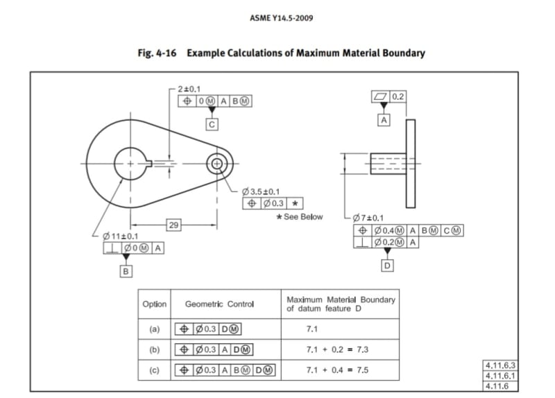
The main purpose was to explain my understanding of the reasoning behind how the MMB is calculated for case (c) of figure 4-16 in Y14.5-'09.

Screenshot_20220507-121858_Drive_fhyjen.jpg


"For a correct analysis of the shape and size of the MMB boundary of datum feature D in option (c), one has to understand the translation and rotation constraining aspects of the relevant datum reference frames, and the step by step establishment process of these datum reference frames.

First, the position and perpendicularity controls for the 7mm pin. The perpendicularity control references datum feature A only, and creates a 7.3 virtual condition boundary for the pin's orientation, not taking into account it's location.

For the position control, a datum reference frame is established constraining 6 degrees of freedom: datum feature A constrains 2 rotations and one translation. Suppose those are u, v, and Z. The first plane of the DRF is established, coincident with datum A. Datum feature B(M) constrains two translations: X and Y and establishes the other two planes of the datum reference frame, intersecting at right angles at datum feature B axis, which is also the Z axis. And here is an important point: these two planes are the origin references for the location of the pin. By now, there is already a cylindrical virtual condition boundary that exists, and the size of this boundary is 7.5mm, as results from the tolerance of location applied and the MMC size. But, this boundary is still not constrained in rotation around the Z axis (datum axis B): it can be anywhere 360° around it, at a fixed distance of 29mm. The tertiary datum feature C(M) doesn't take a part in setting the size of that boundary. What it does is locking its rotation about Z - the w rotation, by orienting one of the planes of the datum reference frame to be at the center of the C datum feature simulator.

So far, there is a 7.3mm boundary for orientation only and a fully constrained 7.5mm boundary for orientation and location.

Next, one has to look at the datum reference frame in option (c). The primary and secondary datum features are the same as in the position control for the pin. Datum reference A is taking care of all rotations but w, and B taking care of the X and Y translations. Which once again, makes for a meaningful location tolerance zone size, even though not all DOF are constrained. Obviously, the datum feature simulator for D, which will have to be basically oriented normal to A, has to be at the worst case size that will contain the datum feature, and take into account it's permissible orientation AND location. Therefore it is not the 7.3mm orientation-only boundary that is relevant. The relationship of datum feature D with A as primary and B(M) as secondary is per the above analysis of the position control applied to it:

The feature must be contained in a 7.5mm cylindrical boundary unconstrained in rotation about Z.

Once this is realized in the form of a datum feature simulator for D with the correct shape and size, it can work as a clocking datum reference for the 3.5mm hole controlled by the FCF in option (c)."
 
Status
Not open for further replies.

Part and Inventory Search

Sponsor