Eng-Tips is the largest engineering community on the Internet

Intelligent Work Forums for Engineering Professionals

  • Congratulations waross on being selected by the Tek-Tips community for having the most helpful posts in the forums last week. Way to Go!

[img http://res.cloudinary.com/engi

Status
Not open for further replies.

holmesss

Structural
Feb 10, 2015
39
0
0
CH
high_stress_chxbzu.png


Hello,
I am doing a static linear analysis on an assembly made of 3 parts as shown in the simplified drawing that I attached.
I am running this assembly in two different scenarios :

1st- Interface AC is glued and ED is glued.
2nd- Interface BC is glued and BA in contact but not glued, ED is glued.

The 3/4 lower portion of parts 2 and 3 is fixed in all directions (As if the two parts are fixed in a rigid mold).

When I ran the analysis on the 1st scenario, I get reasonable values of stress that get to 70 MPa.
When I ran the analysis on the 2nd scenario, I get really high values of stress of 300000 MPa!These values are not very reasonable for me. And they are not located in particular zones (they are not really "singularities") , they are spread around a large area.

Could someone know what could be the problem ?

I can also send you the model in private if it's helpful.

Thank you very much.
 
Replies continue below

Recommended for you

Hello Holmesss,

well, some more logical name of topic would be also helpful:)

I understand that unrealistic stress occurred when you applied frictional contact for a part of surfaces.
I do not know anything about used elements, mesh quality etc. that might be relevant as well, but if we focus only on frictional contact, the very possible reason can be contact setting which define the initial penetration or gap - you can find it in QRG under name INIPENE.
Default setting is "according to geometry" (or similarly, I do not have open Nastran now...), it means if there some geometrical imperfection (artificial peaks), or if there is some offset between parts, this will be considered.
The quickest way is redefine this setting as "set to zero".

And some remarks:
- you haven't defined offset for some region, have you?
- be sure that results were really converged. To get results in SOL101 does not mean you get "final" results, especially if there is frictional contact. Better if you check .f06 file.


Hope this helps,

Jan


With best regards,
Dr. Jan Vojna
Lead Engineer Development

Siemens, s.r.o.
 
@janFEA

Dear Jan,

Thank you very much for your help.
Sorry for the title, I was not able to change it, it came like this by default when I uploaded the image.

I followed your advice and it worked ! I changed the definition to "Zero gap/no penetration", and ran the analysis again and it showed reasonable stress values.
Does this mean that there was gaps between parts in my assembly or not necessarily ?

Thank you once again,

Cheers
 
I think the model thinks BA in scenario 2 is much like a crack. Don't see singularities happening ... over constraint for sure.

another day in paradise, or is paradise one day closer ?
 
@rb1957 It's true ! I want the scenario 2 AB to simulate a crack. You think the very high stress is from over constraint? Does the tips given jan solve my problems in a precise manner or should I change the constraints ?
thanks
 
Hello again,
now I a bit more understand what is the purpose of your model - you would like to simulate a crack or even crack propagation(?).
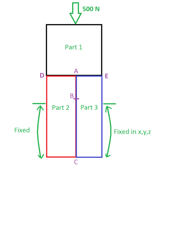
And in your model already initiated crack is between AB.
I guess that unrealistic stress was observed on points A and B, but nothing between, is it so?
Well I afraid it is not so easy...

1. Firstly consider if you really want to simulate it by FEM, maybe BEM could be more convenient - of course I do not know what kinds of solvers are available for you.

2. If this must be done in FEM / NX Nastran, maybe more suitable can be nonlinear SOL601 - although you don't (I think) need to consider nonlinear material, it can be better for convergence because at least you can divide solution to larger number of step.
And there are many function, such as "killing" of elements after exceeding of their defined strength, support of large displacements/strains etc.
BTW, as I wrote you last time:
you used linear static solver SOL 101. Don't believe the results just because there are some - these results cannot be always converged, I mean final (correct, accurate...).
Just open .f06 file and try to find message: CONTACT ITERATION CONVERGED. If there is instead a message something like "the number of iteration was exceeded", then you have unconverged results.

3. I do not know anything about your FE model, but I guess just for approximation to stress/strain results for surrounding A and B, there must be very, very fine mesh...but this geometry is so simply that I would do it by mapped mesh, and then several times refine A and B by element splitting - so there will be only HEXA elements.
You mentioned stress 300.000 MPa - ok, it was on one element, but check the gradient to neighbor - by proper meshing you can decrease it to reasonable value.

@rb1957 - dear rb1957, talking about singularities: sorry I am not a native speaker in English so I don't know precisely what all can be called as singularity in EN. But I guess in 2nd scenario points A and B are actually singular - it is geometrical singularity. Similar to a corner, edge (and 3D they are indeed edges)...and as consequence of this discretisation there is artificial stress peak. Do you agree?

Regards from Prague, guys

Jan

With best regards,
Dr. Jan Vojna
Lead Engineer Development

Siemens, s.r.o.
 
Status
Not open for further replies.
Back
Top