Jhinnie2
Structural
- Sep 28, 2021
- 9
Hi All,
I know there's a lot of threads on impact loads but honestly I'm still confused as there's so many different answers. I have a bolted frame with 360UBs and 230 PFCs, and essentially there are multiple 300kg counterweights in a row which each have a rod running through. Designing for if the chain holding the counter weight fails (which it has failed in the past), these two beams will catch the counterweight with the rod hitting simulatenously so load split 50/50 (ie. to stop it falling into a chute below and damaging the platework). The fall height is 0.4 metres. Based on this V= 2gh = 2.8 m/s.
Looking at two methods here 1. AS3774 Impact loads on hoppers due to dumping, they estimate either 0.1 or 0.3 x (mass x V ) which gives an impact of around 90 to 252 kN total which seems quite high in magnitude? Notabely the counterweight is quite small and compact solid steel.
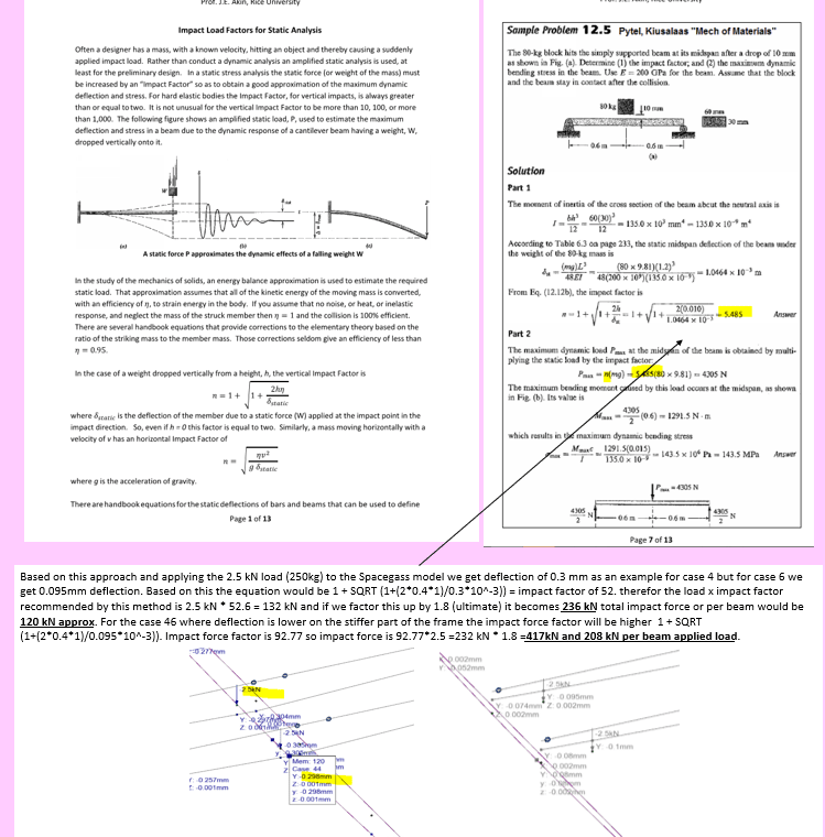
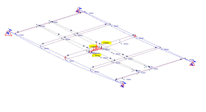
2. method is the kinetic energy = potential energy for the elastic beam. So P = delta x mass x V^2 and for this method I apply a unit load of 100 kN on each of the two beams, and I have moved these loads along the length of the beam to find the worst case scenario to design my frame. Say for example I get 6 mm deflection underneath each beam for these two loads (shown in screenshot), how do I got about back calculating the real world impact force that I should design frame for the impact load case? If delta is 6mm and P is 100 kN, then k = P/delta = 16,667 kN/m. Then how do I back calculate what P is in kN from the 250kg counterweight dropped from 0.4 m above beams?
Thanks
I know there's a lot of threads on impact loads but honestly I'm still confused as there's so many different answers. I have a bolted frame with 360UBs and 230 PFCs, and essentially there are multiple 300kg counterweights in a row which each have a rod running through. Designing for if the chain holding the counter weight fails (which it has failed in the past), these two beams will catch the counterweight with the rod hitting simulatenously so load split 50/50 (ie. to stop it falling into a chute below and damaging the platework). The fall height is 0.4 metres. Based on this V= 2gh = 2.8 m/s.
Looking at two methods here 1. AS3774 Impact loads on hoppers due to dumping, they estimate either 0.1 or 0.3 x (mass x V ) which gives an impact of around 90 to 252 kN total which seems quite high in magnitude? Notabely the counterweight is quite small and compact solid steel.
2. method is the kinetic energy = potential energy for the elastic beam. So P = delta x mass x V^2 and for this method I apply a unit load of 100 kN on each of the two beams, and I have moved these loads along the length of the beam to find the worst case scenario to design my frame. Say for example I get 6 mm deflection underneath each beam for these two loads (shown in screenshot), how do I got about back calculating the real world impact force that I should design frame for the impact load case? If delta is 6mm and P is 100 kN, then k = P/delta = 16,667 kN/m. Then how do I back calculate what P is in kN from the 250kg counterweight dropped from 0.4 m above beams?
Thanks