Eng-Tips is the largest engineering community on the Internet

Intelligent Work Forums for Engineering Professionals

Impact Test Requirement UCS-66 for ASME SA-387 Gr.11 1

Status
Not open for further replies.

Mich_A

Mechanical
Dec 5, 2023
14
0
0
IT
Dear all,
We are designing an Heat Exchanger type AES (split ring) with the following specifications:

Design Temperature SS/TS: 370/354 °C
Design Pressure barg SS/TS: 65.2/82.5 barg
Mimimum Design Metal Temperature Requested by Client: -12 °C
Design Code: ASME VIII Div.1 Edition. 2023

Each part will be made by Gr.11 with:
Plates: ASME SA-387 Gr.11 Cl.2
Forgings: ASME SA-336 F11 Cl.2
Nozzles: ASME SA-335 P11
Standard Flanges: ASME SA-187 F11
Bolts & Nuts in ASME SA-193 Gr.B16 / SA-194 Gr.7

Considering UG-20(f), impact test is required because "Material is limited to P-No.1 Gr.No.1 or 2" and we are under P-No.4 Gr.No.1

We have the following thickness and governing thickness for the hear exchanger:
Part ---- Thickness [mm] ---- Governing Thickness [mm]
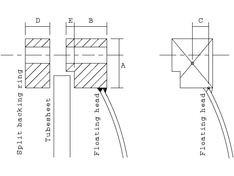
Tubesheet: ---- 105 ---- 26.25 (UCS-66(a)(3))
Floating Cover/Flange/Pass Partition: ---- 125/36/20 ---- 36 (Fig.UCS-66.3)

I've defined ASME SA-387 Gr.11 as Curve B, in accordance to Fig.UCS-66 if produced to fine grain practice, normalized and tempered. Forgings, piping anz girth flanges in curve C, in accordance to "(b) all materials listed in Notes 2(a) and 2(c) for Curve B if produced to fine grain practice and normalized, normalized and tempered, or
liquid quenched and tempered as permitted in the material specification, and not listed for Curve D below" fig-UCS-66.

My questions is, Curve C specifies ASME SA387 Gr.21/22 but not other grades, in fact this material with these grades should be used for hight temperature and in general for hot application.
The same should be for ASME SA-387 Gr.11, in fact, considering the thickness indicated I obtain as MDMT +9°C, that is pretty hight. Why is it not accepted and listened in Curve C with this grade?

Furthermore, my governing thickness is given by the floating cover with 36 mm, our client asked MDMT at -12°C, so should I test the material at this temperature or below this temperature?

I cannot use any help to decrease my MDMT calculated (using for example Table UG-84.2 or considering PWHT or more refering to fig. UCS-66.1 and its calculation)

Thank you in advance
 
Replies continue below

Recommended for you

OP,
Fig UCS-66 material groups A,B,C,D are based on brittle fracture characteristics of materials starting Group A starting with higher risk to Group D reducing the risk.
It is not necessary that all the grades of the same material SA 387 will fit into the same group.
Group A is for low toughness and materials that don't fall into any other groups.
Group B- where most materials will fit,
Group C- for low strength materials. Example SA 516 Gr 60. Grade 70 will fall in Group B.
group D- Tough fine grain steels, normalized, Q&T etc.

As the strength of material increases, so does the risk of brittle fracture, particularly as thickness increases. Higher absorbed energy is required for stronger materials (UCS-84.1)

Thickness, stress, welding residual stresses and weld defects contribute to the risk of brittle fracture. Following provides assessment for these risk factors:
1. Fig UCS-66 - thickness
2. Fig UCS-66.1 - stress
3. UCS-56 - residual stresses (no credit for temperature reduction if PWHT is required by Code rules).
4. UCS-57- welding defects

The client provided MDMT of -12C is only Arbitrary MDMT (UG-20(f)). You must prove that the vessel MDMT is at or lower than -12C
Vessel MDMT will be the warmest MDMT for all individual pressure containing parts. This MDMT shall correspond to the vessel MAWP.

Hope the above info helps.

GDD
Canada
 
Thank you so much! Absolutely these info have been really useful. I hadn't considered the brittle fracture characteristics of Gr.21/22 and Gr.11.

So, considering the MDMT, if I have forgings with MDMT at -32 [°C], Tubesheet at -29 [°C] and for example tubes at -49 [°C] but plates at +9 [°C] I must test plates at MDMT of -12[°C] to prove that the vessel MDMT is at or lower than -12 [°C]. Have I understood right?

An update in data:
Design Pressure barg SS/TS: 37/55 barg
 
OP,
You are right. Don't forget to include the nozzles and the flanges in your assessment. I don't understand when you say I ahve forgings with MDMT -32C.

You must account for all pressure parts including channel head, shell, heads, nozzles, tubesheet etc while determining the MDMT.

GDD
Canada
 
Thanks GD2 for your answer,

"I don't understand when you say I ahve forgings with MDMT -32C."
I'm sorry I haven't explained myself appropriately, I made an exemplation, so in my case using fig.UG-66 (tube side) I obtain, for that thickness and for forgings in ASME SA-336 Gr.11, a MDMT of -32 [°C].
 
Regarding the Impact test, I have a doubt about the governing thickness reported in Fig. UCS-66.3.

Considering the following images, our software considers the following governing thickness of the floating flanges:
- Slit ring divided for 4,
- Floating flange: dimension B divided for 4
- Thickness of the floating cover

In accordance to Fig.UCS-66.3, should the thickness of the flange being considered (slit ring and floating flange welded)? Or should I consider the governing thickness given by the floating cover with the split ring as separate component? Moreover, in my opinion the split ring should be considered shell side instead of tube side, and how would the governing thickness of the split ring be defined?

he_floating_head_u82ynk.png


Considering a different case, with carbon steel (ASME SA-516 Gr.70 for plates and ASME SA-765 Gr.II for forgings), in accordange to Fig.UG-84.1M, SA-765 has the minimum impact test reuired at -46°C, but in accordance to fig. UCS-66(3), I should consider only the minimum hub thickness.
My queston is, am I wrong if I consider oly the single component (flange), giving it satisfied for UG-84? Considering obviusly the plate for its thickness in curve D (UCS-66). Or, should I consider the MDMT obtained from plate also to evaluate the flange shell to cover? Regarding that, when I report that in a table, may I consider the flange joint with governing thickness and MDMT obtained from the governing component or would be better to distinguish them with component and material?

Thank you so much in advance
 
OP,
You have asked a bunch of questions in one place.
My first question is - is the backing device (split ring) and the floating head flange even correct? Usually, the split ring should have the step going over the tubesheet OD. The floating head flange face should be straight with the pass partition gasket coming in between the tubesheet and the floating flange.

In regards to picking up the governing thickness by the software, it is correct.

On Fig UG-84.1M, it;s all about impact test requirements for Charpy Test. Where do you get -46C from? Charpy tests have to be done at specified test temperature by you, which should be at or colder than the vessel/HX MDMT.

GDD
Canada
 
Thank you GD for your answer,


I just shown an imagine where spit ring (back ring) had a generic indication. Our floating flange will not be absolutely that.

Thank you so much!


From Fig.UG-84.1
(c) Material produced and impact tested in accordance with SA-320, SA-333, SA-334, SA-350, SA-352, SA-420, impact tested SA/AS 1548, SA-437, SA-540 (except for materials produced under Table 2, Note 4 in SA-540), and SA-765 do not have to satisfy these energy values. See UCS-66(g)

From UCS-66(g)
(g) Materials produced and impact tested in accordance with the requirements of the specifications listed in Figure UG-84.1 (Figure UG-84.1M), General Note (c), are exempt from impact testing by the rules of this Division at minimum design metal temperatures not more than 5°F (3°C) colder than the test temperature required by the specification.

ASME II:

TABLE 4
STANDARD IMPACT TEST TEMPERATURE FOR
STANDARD SIZE [10 by 10 mm] SPECIMENS
SA-350 Gr.LF2, Class 1 −50 [−46]

TABLE 3 Charpy V-Notch Impact Requirements
Test temperature of SA-765 Gr.II F(°C) −50 [−45]
in that case with this note:
--> Actual test temperature should be established at time of order. If no temperature is specified, tests will be made at test temperatures shown in this table.

From the following threaded:

 
Op,
You have all the information. What are you awaiting for?

Simply, apply the rules of the Code and proceed forward.

For example: SA-765 Class II will be factory impact tested by default at -45C. By rule of UCS-66(g), the material will be good up to MDMT of (-45C-3C)=-48C. You don't have to care about the energy value given in UG-84.1 and retest the material for Charpy. By material specification, SA-765, it's all done. Just verify the MTR for the impact test requirements per SA-765 with chemical composition and mechanical properties.

GDD
Canada
 
Status
Not open for further replies.
Back
Top