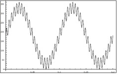
"I still think this is like a FFT type waveform where one sinusoid is used to make the other, but I need some way of generating that function. This isn't clear to me. "
The two sinusoids don't need to be related, in fact as I said earlier the amplitude of each needs to be independently adjusted. An electronics guy would find it trivial to generate this signal. In simple terms you could think of it this way:
Use two signal generators - one to generate each sinusoid. Feed the two signals into a summing amplifier. Job done. As you say, this part could be done open loop - simply adjust the amplitude of each sinusoid until the pressure waveform is correct.
Maintaining the correct "DC" pressure level probably needs to be closed loop for a 3 hr test. Alternatively since there are no potential leakage sites and DC drift will probably be mostly thermal, it may be sufficient to check the apparatus every 10 minutes and manually pump the pressure back up.
Your first diagram is not clear but it looks like the peak-peak limits of your pressure envelope are 0 - 300 psi? From the wording of the problem, I would have assumed a 0 - 300 psi waveform with 0 - 90 psi waveform superimposed for an overall envelope of 0 - 390 psi p-p.
je suis charlie
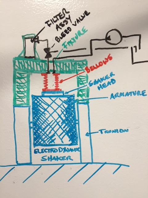
 . Does anyone know of a way to generate this waveform. I need to be able to input a vibration controller and run it "open-loop" to drive the pressure into a bellows assembly to generate this waveform, but I need a function...??? PLEASE HELP!