Continue to Site

Eng-Tips is the largest engineering community on the Internet

Intelligent Work Forums for Engineering Professionals

  • Congratulations KootK on being selected by the Eng-Tips community for having the most helpful posts in the forums last week. Way to Go!

In-plane buckling analysis of a steel arc 1

Status
Not open for further replies.

nivoo_boss

Structural
Jul 15, 2021
130
Hey everyone!

Perhaps you can give some advice on how to check if this steel arc will buckle under the specified ULS load. It's created in SCIA Engineer software. It has a span of 45 m. It's like a 1 m high steel truss with U-sections for chords and L-sections for brace members.

If you can point me to some hand calculation methods for this analysis, I would be grateful as well. But perhaps you can give me some advice on how to approach it in software? I can make stability combinations in SCIA and then it calculates me any amount of buckling modes I specify with a factor alpha_cr after them - basically it should mean that the structure will buckle under my load factored by that alpha critical factor.

A picture from my calculation model:
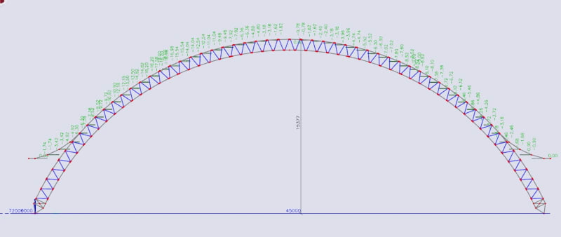
steel_arc_vofrvf.jpg
 
Replies continue below

Recommended for you

Software method: The elastic buckling analysis will give you the critical load. You use this to calculate the slenderness parameter that your design code uses for axial compression buckling (column buckling), then do the usual code checks for beam-columns. In the Australian/NZ codes, the slenderness parameter is Le/r but I think Eurocodes use something else. This blog (by forum member Agent666) shows how to do it in Aust/NZ and may help even if not your own code.


Hand check:
Apply dead load, plus live load to one half of the arch.

Calculate axial force and moment at quarter span.

Take Le = half the length around the arc.

Run your usual code checks for beam-columns.

I would use first-yield as the capacity for a new design but might be too conservative for an existing arch.


I also have a document that refers to charts in EN1993-2 but I've not seen them myself.
 
Thanks. But please elaborate:

"Apply dead load, plus live load to one half of the arch." - Why only half? Or do you propose I look at it as an inclined beam with a span of half the arc length and calculate internal forces for that inclined beam?


only half to give you an unbalanced load that would promote buckling of the arch.

Rather than think climate change and the corona virus as science, think of it as the wrath of God. Feel any better?

-Dik
 
Long ago, I had "inherited" a design approach that designed curved beams for axial loading by treating them as straight columns and applying normal column buckling formulas to them. Which sounds like the approach recommended above. Only, those column formulas are all derived assuming a straight column, and I can't think of any reason why they would, or should, be applied to an arch. Is there any justification for that, other than lack of better information?
There are formulas for buckling of circular rings under symmetrical radial loading, which is similar to the arch example, but not similar enough to directly apply the results, either.
 
Nivoo: Analyse the arch, not a notional inclined beam. Textbooks should also have equations, maybe Roark's Formulas (but I haven't checked).

JStephen, how did the axial force get into your curved beam? Are you talking about concentrated loads at each end pointing towards each other, rather than tangential to the curve?

The hand check I mentioned is just a check. There's a computer model that can be used as the primary analysis.

I should have noticed earlier that this appears to be a circular arch. Gravity load will cause bending in the arch, so a second case of load over the full length should also be checked. The half-length load tends to be critical for parabolic arches because uniform vertical load doesn't cause bending.
 
You pretty much have to analyse the arch with a computer simulation. None of the elastic arch formulae accommodate the loss in stiffness due to the 'stick' web members... same thing with lattice braced column sections, although the lattice braced column sections have formulae for solutions. Second order effects can be real significant.

Rather than think climate change and the corona virus as science, think of it as the wrath of God. Feel any better?

-Dik
 
steve49 said:
You use this to calculate the slenderness parameter that your design code uses for axial compression buckling (column buckling), then do the usual code checks for beam-columns.
JStephen said:
Only, those column formulas are all derived assuming a straight column, and I can't think of any reason why they would, or should, be applied to an arch. Is there any justification for that, other than lack of better information?

The column buckling formulas and L/r ratios and such tend to fall apart for complex structures that don't fully match the assumptions. This is one reason why the codes (at least the Eurocode and the US AISC code) now put more effort into a geometric nonlinear analysis of the structure... Often using "notional loads" to impart an initial deformation.

In my opinion, the best way to do this with your structure is to perform an "elastic buckling analysis" in SCIA similar to what steve49 suggested. This will give you a good idea of the general "shape" of the buckling mode. Then I would introduce some "initial imperfections" along the length of your arch (maybe scaled to 1/500 of the arch span). Then when you do a geometrically non-linear analysis you will capture this buckling (or the effect of this buckling mode at lower force levels) directly in your analysis.

What else?

Oh yeah, this method I describe does a good job at capturing the elastic effects of buckling. But, since steel structures tend to fail via inelastic buckling, it will not be perfect. AISC has some member stiffness reductions that they impart on members in order to approximate the effects of inelastic buckling in an elastic analysis. I'm not sure if the Eurocode has anything similar or not because it's been awhile since I've looked at it.
 
Thanks for the help.

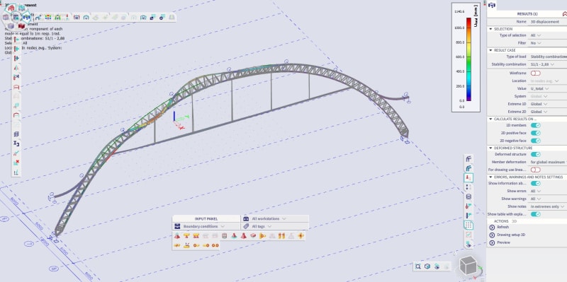
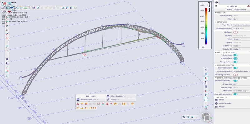
So I performed a linear stability analysis, I did 15 buckling modes. The first mode, with a factor of 2,88 times my asymmetric ULS load, the arc's top chord buckles out-of-plane - but in reality this cannot happen since the top chord is stabilized with load bearing sheeting, it's hard to define that in my model though. The second mode has a factor of 5,28 and the bottom chord buckles out-of-plane between longitudinal bracings (there are seven of these along the arc, I put supports at these locations). And after that starting from mode three with a factor of 5,85, the L-section brace members start to buckle here and there. Nothing happens in-plane to the chords in these 15 modes at least.

So what should I do next? :) I put a screenshot down here of the first and second buckling mode. As for the "initial imperfections", I'm not sure how to enter them, since the arc is made out of like 57 shorter members per chord.

The first buckling mode.
1st-buckling-mode_aoptba.jpg


The second buckling mode.
2nd-buckling-mode_uugvzj.jpg


EDIT: Okay, so I played around with it a little. I added an "intial imperfection" to each small segment of the arc's chord and the web members as well. You can set it so the software takes it from EC3, and it should be L/200 for my chord members at least.

So I performed non-linear buckling analysis with these settings and everything remains the same, though the factors are lower now of course - for the first buckling mode it is 2,0 and for the second one it is now 3,56. So is this fine? Can I say the arc does not buckle under my ULS load in-plane? The governing buckling modes are out-of-plane?
 
Nivoo, what's the buckling factor for mode 15? Is it much larger than mode 3, or is there a bunch with similar load factors?

I would still continue until in-plane buckling occurs and check against hand calc, or some other way of checking the computer analysis.


Josh, what would you do after the second order analysis? This structure doesn't qualify for advanced analysis due to the channel and angle sections (even if you have software that passes the torsion analysis requirements - mine doesn't) so you need an effective length for compression checks.
 
steveh49- My application was curved radial rafters in a dome-roof tank, with compression ring at the center, tension ring at the shell. Assuming pinned connections at each end, you can find all the internal forces and moments- the issue was, none of the codes specify an allowable load or moment for that configuration.
 
"Nivoo, what's the buckling factor for mode 15? Is it much larger than mode 3, or is there a bunch with similar load factors?"

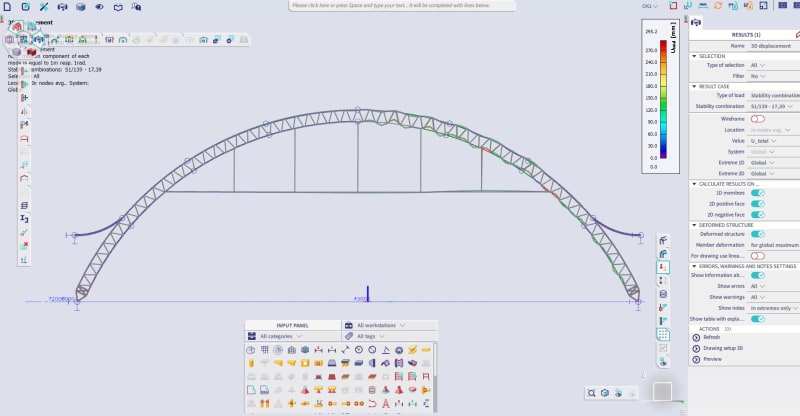
There are a bunch of similar factors. So I did like 200 modes and number 139 seem more like in-plane buckling at 17,39 times the ULS load:

139th-mode_bbgvdh.jpg


"I would still continue until in-plane buckling occurs and check against hand calc, or some other way of checking the computer analysis."

Okay, so in that case I think I should make a new model that's not a truss but rather a single curved member of a lot of sections to get the bending moment.
After that I think I would take the buckling length from EN 1993-1-2 that covers arcs. But what then - should I check that length as member in compression and uniaxial bending?
 
For a hand solution, you may want to see 'Guide to Stability Design Criteria for Metal Structures'. They have formulas for a variety of loading types.
 
steve49 said:
Josh, what would you do after the second order analysis? This structure doesn't qualify for advanced analysis due to the channel and angle sections (even if you have software that passes the torsion analysis requirements - mine doesn't) so you need an effective length for compression checks.

There are multiple types of buckling. Individual member buckling would still be done using the unbraced length of the individual member. It's the overall buckling (or moment magnification) of the arch that will get captured by a 2nd order analysis that includes initial imperfections which mimic the global buckling mode.

Global buckling isn't usually checked using unbraced lengths. Though you could mimic this by coming up with "effective" moment of inertia, effective area, and an effective unbraced length. In many ways, the method I described is a good way of developing what the "effective" unbraced length is from something like this. Though you could also do this by looking at the distance between inflection points in the buckling mode that you solved for.
 
OP said:
but in reality this cannot happen since the top chord is stabilized with load bearing sheeting, it's hard to define that in my model though.

You need to add a some lateral restraints (or springs) to represent the roof. At present you are not finding the buckling solutions that will occur with a roof in place.

Be mindful of the level of stability that will occur during erection. You need to model that too. You don’t want the arch failing before all the roofing goes on.

The Wembley football stadium arch is similar, and just about sent the builder broke due to problems erecting it, and led to massive disputes between builder and consultant.
 
Tomfh said:
Be mindful of the level of stability that will occur during erection. You need to model that too. You don’t want the arch failing before all the roofing goes on.

That's brings up a question that sometimes troubles me..... Generally speaking, we try not to dictate "means and methods" to the contractor for how they're going to build something, right? That's because we don't want to take responsibility for the construction. But, there are cases where this becomes very important to the structure and to the project.

Where do we draw the line?

My tendency is to believe that this has to be specified in the contract. If we're not designing the methods of erection, then our drawings will dictate to the contractor and recommend that they they need to hire an independent engineer to design their temporary shoring or such.
 
JoshPlumbSE said:
That's brings up a question that sometimes troubles me..... Generally speaking, we try not to dictate "means and methods" to the contractor for how they're going to build something, right? That's because we don't want to take responsibility for the construction. But, there are cases where this becomes very important to the structure and to the project.

Where do we draw the line?

My tendency is to believe that this has to be specified in the contract. If we're not designing the methods of erection, then our drawings will dictate to the contractor and recommend that they they need to hire an independent engineer to design their temporary shoring or such.

The answer to this is one of the first lessons my former steel professor ever gave me: Buckland's law (he worked for Buckland and Taylor before heading into academia). Buckland's law states that the engineer must be able to envision at least one way - not necessarily an economical way - in which the structure they designed could be erected. If the designer did not do so and the structure could not be erected safely, that's on the engineer. If it could be, but the contractor didn't bid it that way / couldn't conjure up another way to do it safely, that's on them.

As a contractor that's exactly how I feel about the topic today. Give me a design that's buildable and I will build it. If I cant or I mess up the pricing, that's on me. If you give me a POS that cant be built, that's on you.

I am saddened that I didn't appreciate my prof as much as I should have in school. Decades later I still refer to my hand written notes of his lectures. The dude was a treasure (a tad intoxicated at this moment so forgive the remembrances).
 
That's brings up a question that sometimes troubles me..... Generally speaking, we try not to dictate "means and methods" to the contractor for how they're going to build something, right? That's because we don't want to take responsibility for the construction. But, there are cases where this becomes very important to the structure and to the project.

Where do we draw the line?

I generally have a CYA note in my drawings saying they [the contractors] are responsible for stability during erection/building. But I feel I feel I have a obligation to alert them to certain (unusual) things.

I typically make it clear in my bid that we aren't providing engineering for lifting every piece. (Or bracing the structure during construction.)

 
It's a pre-existing arc. The building's been renovated.
 
Status
Not open for further replies.

Part and Inventory Search

Sponsor