Continue to Site

Eng-Tips is the largest engineering community on the Internet

Intelligent Work Forums for Engineering Professionals

  • Congratulations KootK on being selected by the Eng-Tips community for having the most helpful posts in the forums last week. Way to Go!

Inclined Column Question 1

Status
Not open for further replies.

Ashke15

Structural
Mar 9, 2023
16
Hi everyone, I'm looking at a situation I haven't encountered before and wanted to get some feedback if you have some time.

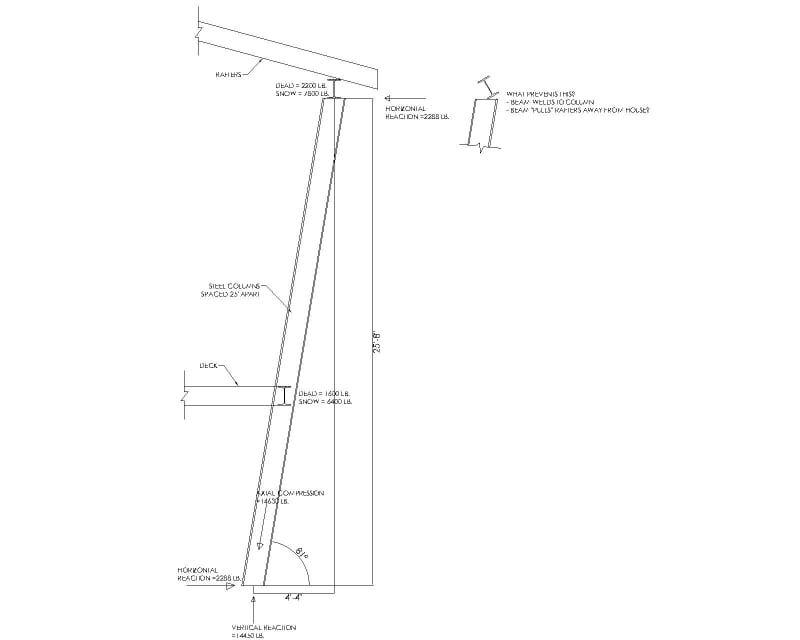
I've got a large custom home in a high snow load area with a covered deck at the back. The deck is 25' wide and has an inclined steel column at each end. There will be a beam at the top to carry the roof and a beam at the deck level. I have resolved the loads into axial compression in the column, vertical reaction at the bottom, and horizontal reaction at top and bottom using the D + .75S + .75L load combination. My question concerns the horizontal reaction at the top of the column. What prevents the beam from rotating as it tries to resist the horizontal force from the column?

The beam of course welds to the top of the column. It appears to me that the column tries to rotate the beam away from the house. The welds hold the beam in place, but then the beam tries to pull the rafters away from the house. Is this the correct load path? I need to make sure that the rafters are secured appropriately to the beam and back at the house so that the beam doesn't pull away from the rafters, and so that the rafters don't pull away from the house. That's how I see it, but wanted to see what you think. Do the deck joists see any of that force pulling them away from the house? Would appreciate any feedback. In summary:

1) The beam rotation is resisted by the welds from the beam to the column? I will also have web stiffeners.
2) The beam imparts a horizontal force on the rafters pulling them away from the house?
3) Do the deck joists also pull away from the house?
4) Recommendations from your experience?
5) Is there a certain degree of incline where you need to design the column with a moment at the base instead of only vertical and horizontal reactions?
6) Where did I mess up?

Thanks!
Inclined_Column_mlbm9b.jpg
 
Replies continue below

Recommended for you

Well, to be fair, I can afford to guess. OP can't. I would obviously not leave it to guessing if this were my project to see through.

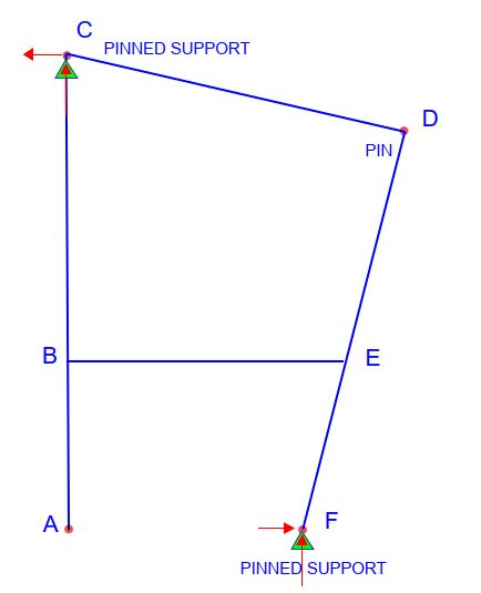
I don't think it was ever made clear by OP which joints are necessarily pinned vs. fixed. In assuming that they're all pinned, I was speculating whether or not the frame would be stable in the in-plane direction. At first I thought the answer would be an obvious no, but I'm not sure that's necessarily correct due to the trapezoidal geometry. Perhaps this is off topic.

And OP, please don't guess!
 
My original sketch was not finished, so I'll finish it now. There is a difference between a free pin and a pinned support. Joints C and F are pinned supports; joint D is a free hinge, meaning it cannot resist moment, but it can move if the structure permits. Column DEF is continuous from end to end.

Without pinned supports at C and F, I agree the structure is unstable.

Capture_m0e2ve.jpg
 
If the frame line isn't meant to be a lateral frame, perhaps the load can be taken into the diaphragm and distributed to other lateral resisting elements. If not, then I would definately look towards making a steel frame with dual purpose of supporting the inclined column and resisting lateral loads.
 
I actually designed this originally assuming that column DEF would be fixed at the bottom. But when I was getting a connection at the bottom with a 2" thick base plate, (8) 1" diameter bolts, and a 7'x7' footing for overturning I thought I should try the pinned connection. Maybe I should design the top as if it's pinned and still go with the moment connection at the bottom to be ultra conservative
 
If an isolated footing at the base resisting moment you'd do well to get an almost uniform bearing pressure. Permanent eccentric loads on the footing can create a settlement issue... You don't want one side of the footing to settle at a different rate than the other. I'm leary of the fixed base approach tbh.

** Perhaps a grade beam on elastic foundation would be a better moment resisting element.
 
If the existing house can't take the horizontal load at C, forget about an inclined column. Fixing point F with a 2" thick base plate and 7'x7' footing is a terrible solution which will lead to unacceptable deflection at point C.
 
BAretired said:
Fixing point F with a 2" thick base plate and 7'x7' footing is a terrible solution
Tell me how you really feel lol. Why would there necessarily be deflection at point C? Because of settlement at the footing like driftLimiter is saying?
 
I would probably design joints B, C, D, and E as moment connections and see how that works. Then, also tie into the floor diaphragms of the main building for redundancy.

(What I was contemplating above is whether the frame would be stable if joints B, C, D, and E were free pins and joints A and F pinned supports. I think it would be, although I wouldn't design it this way. Just a thought experiment.)
 
Ashke15 said:
Tell me how you really feel lol. Why would there necessarily be deflection at point C? Because of settlement at the footing like driftLimiter is saying?
Either point C is a pinned support or it's not. If the existing house can't resist a horizontal force of 2258#, then it isn't an adequate support. It may be more like a roller than a pin, which means that it can't be relied upon to resist any horizontal force. You would be relying on fixity at F to support a 26' high cantilevered column which would bend, causing large horizontal deflection at points D and C. Uneven settlement of the footing would not help either.


Or just cut a notch in the rafters?

And fix the beam at 90 degrees to the end of the inclined column?

Remember - More details = better answers
Also: If you get a response it's polite to respond to it.
 
human909 said:
I'd also note that people aren't eager to have their home look like an oil refinery.

I do realise this was meant in jest, but it just seemed to me that everyone is overthinking this and coming up with all manner of bracings and designs without knowing if the dimensions, position and angle of all the components can't be moved a little bit.

IF CD angle to DF was 90 degrees that seems a very small adjustment. Why does the top beam need to be vertical?

Remember - More details = better answers
Also: If you get a response it's polite to respond to it.
 
Ashke15 said:
I actually designed this originally assuming that column DEF would be fixed at the bottom. But when I was getting a connection at the bottom with a 2" thick base plate, (8) 1" diameter bolts, and a 7'x7' footing for overturning I thought I should try the pinned connection. Maybe I should design the top as if it's pinned and still go with the moment connection at the bottom to be ultra conservative

It would not be ultra conservative. It would not be even slightly conservative. If the existing residence can't resist the horizontal force, a cantilevered column would not be much help. The horizontal force at D was 2288# which would be, say 1144# at each inclined column.

The fixed end moment at the bottom would be 1144*27 = 29,700'#. If adequately braced, you might try W8x15 with a moment resistance of 32.4'k for the inclined column. If the existing residence cannot resist the force, deflection at D would be PL^3/3EI = 1144(27*12)^3/(3*29e6*48.1) = 9.3" which is out of the question. Any footing rotation would magnify deflection at D. A much stiffer structure is required.

Consider it carefully, as you will be in serious trouble if point C is not capable of acting as a pinned support.
 
Answers to your questions:
1. Forget about beam rotation. Instead, you need a brace beam connecting to the top of column perpendicular to the edge beam. (The edge beam you are now showing does not brace the top of the column.)
2. Yes. The beam mentioned in response to question #1 (functioning in part as a brace beam) will have a horizontal force.
3. The top of the column will pull away from the house unless there’s a valid load path for the axial load in the (new) brace beam.
4. Provide the brace beam as noted in answer to question #1 and provide a load path to resist (and counteract) the axial load in the brace beam.
5. No
6. You did not mess up. You just did not finish addressing the load path for the axial force in the brace beam. What will resist the axial load? (A braced frame? A moment frame? A counterbalancing leaning column? (Although you will never be able to precisely balance the axial load with an equal and opposite force.))
 
Status
Not open for further replies.

Part and Inventory Search

Sponsor