Continue to Site

Eng-Tips is the largest engineering community on the Internet

Intelligent Work Forums for Engineering Professionals

  • Congratulations KootK on being selected by the Eng-Tips community for having the most helpful posts in the forums last week. Way to Go!

Incomplete or profile general note applicable

Status
Not open for further replies.

Kedu

Mechanical
May 9, 2017
193
What is your opinion about this drawing?
Are datum feature B and datum feature C fully defined or are incomplete? Otherwise stated, is profile general note (profile|3|A|B|C|) applicable to "B" and "C" datum features?
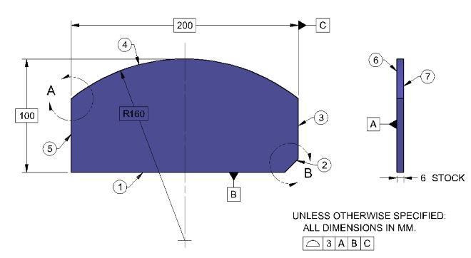
INC_-_Copy_ebccaf.jpg
 
Replies continue below

Recommended for you

Yes, I meant 5.2(c) -- previous post has been edited/corrected.
Thanks, Frank!

John-Paul Belanger
Certified Sr. GD&T Professional
Geometric Learning Systems
 
Kedu,

Datum features B and C on the L-shaped part drawing are not features of size, because the datum feature labels are not directly in line with the dimension lines.

Evan Janeshewski

Axymetrix Quality Engineering Inc.
 
Belanger said:
I would say that your datums B and C are not directly opposed, so they are not covered by Rule #1 and thus they get the general profile tolerance.

John-Paul Belanger,

Why those two datum features (which lets pretend are not covered by rule#1) are getting the general profile?
What rule#1 has to do with the relationship between features (a.k.a. mutual relationship between primary and secondary -maybe perpendicularity, or relationship between tertiary datum feature and its higher precedence datums)?
I do not think that there is any relationship, therefore, rule#1 enforced or not, it's a moot point. Rule#1 wouldn't establish anyway any orientation relationship (of datum feature B) to the primary. The same for C.

Again, I am asking the question from the REQUIRED relationship between datum features (secondary to primary and tertiary with primary and secondary).
Also, what rule#1 has to do with the enforcement of the UOS (default profile) onto the datum features B and C?


Evan,

axym said:
Datum features B and C on the L-shaped part drawing are not features of size, because the datum feature labels are not directly in line with the dimension lines.

I know that, but you did not answer my question: Are the datum features B and C subject to the default profile note?
If answering this question in a direct way will create some sort of controversy, I understand that, and I will accept that you do not want to go there. I was just curious how would you answer it. Is this another swamp?

John-Paul Belanger,
In this discussion, looks like Evan it saying that the rule#1 is applicable EVEN if the features are not totally opposed.

axym said:
axym (Industrial)
15 Sep 15 17:00
greenimi,

I'm glad that the thread is getting to some interesting outcomes. Your questions tend to make us dig deep and extract the subtle details. Keep in mind that the writers of GD&T textbooks and exercise books (and even standards) can only get into the intricacies to a certain extent, without losing most of their audience. People want things to be simple and easy, not complicated and difficult. I know from experience that it is much easier to make money glossing over these subtleties than it is addressing them. I'll stop there before I get into a self-righteous, bitter rant ;^).

CH,

I would say that Rule #1 still applies, even with features that are not perfectly opposed. Assessing the feature's conformance to a boundary is straightforward, even if the feature has unopposed areas.

Again, to me the difficulty lies in the actual local size. It's an old, shop-worn tolerancing tool that serves well for parts that one wants to be able to inspect with a caliper or mic. But for this tool to work, certain conditions have to be in place (such as opposed geometry, and form error that is relatively small). When these conditions are not satisfied, it breaks down and becomes ambiguous. It's just not as robust as zone-based geometric tolerances.
Evan Janeshewski

Axymetrix Quality Engineering Inc.
www.axymetrix.ca


Evan,
Are you maintaining your opinion shown above? Again, just for my own edification.


All,
Which datum feature is REGULAR feature of size in fig 7-40/2018.
Figure 7-40 Irregular and Regular Features of Size as Datum Features
Again, I am talking about the datum features (don't came back and say the holes are regular FOS in that figure, because the holes are not datum features)
 
Kedu said:
Why those two datum features (which lets pretend are not covered by rule#1) are getting the general profile?
Kedu said:
Also, what rule#1 has to do with the enforcement of the UOS (default profile) onto the datum features B and C?
Rule #1 is by definition a way of controlling form. So if Rule #1 does not apply on a particular feature, we appeal to another form tolerance (unless it's an independency thing, which is not pertinent to your example).
If Rule #1 is not invoked on datum features B and C, then we naturally fall back on the profile tolerance to control form/flatness of those two sides. (There may be some unusable portion of the profile zone on those two surfaces, but that was addressed in the earlier portions of this thread.) What else would control any bumps on those two surfaces?

That was the main answer to your question. But... now we need to examine whether Rule #1 does or does not apply to your datum features B and C. I think ASME would say that Rule #1 applies by default to a "regular FOS." In my post I walked through the definition of a regular FOS (which involves "opposed" elements). That's how I arrived at my answer.

Evan was getting into the conditions for Rule #1 more deeply, since I notice he used the qualifier "perfectly opposed." In that other thread he dives into the definition of actual local size, which could help us here. I notice that my own view on that thread changed somewhat, and maybe we should study that thread to avoid rehashing more details here.


John-Paul Belanger
Certified Sr. GD&T Professional
Geometric Learning Systems
 
Kedu,
The title of figure 7-40 should not mention anything about regular features of size, because none of the datum features shown in that figure is a regular feature of size. This is just another example of editorial mistake made in the new version of Y14.5.

Regarding the drawing showing the L-shaped part... the 50 and 60 dimensions should have never had +/- tolerances in the first place as +/- dimensions should be reserved for regular features of size to avoid specification ambiguity.

In my opinion, the whole concept of general tolerance defined like this is a swamp. There are for sure cases where this works quite seamlessly, but I have no doubts that there are also cases where trying to figure out what callout on the drawing is responsible for what is tough thing to do. So as long as the committee does not define clear rules for the interpretation of this type of general tolerances, I am afraid that any opinion is just a best guess.

For what it is worth, I think the concept of regular and irregular features of size (especially the way these terms have been used/defined/shown in the standard) is a swamp too.

J-P,
Just as an academic exercise... Let's imagine that the part geometry is such that the height (60 +0.5/0) and width (50 +0.5/0) are undoubtedly regular features of size and so that the Rule #1 undoubtedly applies. Couldn't the general profile be still applicable to datum faces B and C as an orientation (not form) control?
 
Pmarc -- your swamp comment summarizes the entire thing.
And yes, since Rule #1 is for form, I suppose the orientation aspect of those surfaces would appeal to the general profile.

John-Paul Belanger
Certified Sr. GD&T Professional
Geometric Learning Systems
 
Pmarc said:
... Couldn't the general profile be still applicable to datum faces B and C as an orientation (not form) control

Yes, that's I am talking about. Controlling the relationship of the secondary to the primary ( orientation) OR the tertiary datum feature to the primary and secondary, WITH the default profile UOS....looks strange to me: UOS to be used as a "catch all" ...if a designer missed something ...don't worry: default profile has it for you.

The same "conclusion" has been drawn in the other forum I was posting this question however I am not sure if that WAS the original intent of the committee. But again, looks like it was, since some pictures from 2018 (11-21) support with theory.

Looks like the more we learn, the more swamps we find. The same is in life: the more you dig the more worms you get.
 
pmarc,

Out of curiousity, what about Y14.5-2018 fig 7-40 datum feature C do you believe does not satisfy the definition for rFOS? It is a set of opposed parallel surfaces and it is associated with a directly toleranced dimension per 5.2(c) (geometric tolerances), as it now as of 2018 has explicit profile tolerances applied to each surface. I could see B not being considered a rFOS as it does not have any tolerances applied.

JP,

Thank you for pointing out 5.2(c) (and as a result 2.2(c) in 2009 as well). I had forgotten about that section, the only thing that usually came to mind was the verbiage contained in the "definitions" section for directly toleranced. I would agree, taking into account Y14.5-2018 para 5.2(c) the basic dimensions associated with profile tolerances in fig 7-40 would seem to fall under directly toleranced dimensions (A and C, for whatever reason B still lacks an applied tolerance - geometric or +/-).

As a general question to all,

Considering the broad definition in Y14.5-2009 para 2.2 and Y14.5-2018 para 5.2 for directly toleranced dimensions, what kind of tolerances would NOT fall under "direct tolerancing methods" ? I am thinking general tolerances applied in a note like the ones above (UOS 0.5 profile to |A|B|C| ) or a general tolerance specified in the title block (such as x.xx +/-0.05 for 2 decimal place dimensions).

That said, I'm not sure understand conceptually why a feature defined with these "indirect" methods should disqualify a feature as a FOS other than it is specifically stated as such.
 
Chez311,
The requirement of "associated with a single directly toleranced dimension" is not fulfill in fig 7-40.
Paragraph 5.2 is talking about DIRECT TOLERANCING METHODS.

So, here we are in pmarc's swamp:) Aren't we?

Per what I know, currently, ± should be used in order to consider a feature as being rFOS.
If basic is used (instead of ±), then rule#1 is not applicable even the feature has the qualifications of rFOS (opposed and parallel......) because in that case perfect form at MMC is required AND also perfect form at LMS LMC is required too.


chez311,
See greenimi's response.

greenimi,
I wish it was my swamp. I could have drain it by myself.
 
chez311 said:
I would agree, taking into account Y14.5-2018 para 5.2(c) the basic dimensions associated with profile tolerances in fig 7-40 would seem to fall under directly toleranced dimensions (A and C, for whatever reason B still lacks an applied tolerance - geometric or +/-).

As a general question to all,

Considering the broad definition in Y14.5-2009 para 2.2 and Y14.5-2018 para 5.2 for directly toleranced dimensions, what kind of tolerances would NOT fall under "direct tolerancing methods" ? I am thinking general tolerances applied in a note like the ones above (UOS 0.5 profile to |A|B|C| ) or a general tolerance specified in the title block (such as x.xx +/-0.05 for 2 decimal place dimensions).

Y14 5-2018 introduces a definition which clarifies what directly toleranced dimensions are. See 3.27.

According to it, basic dimensions are not directly toleranced dimensions whereas dimensions to which a general plus/minus tolerance applies are.

Also, I would say that there is a difference between directly toleranced dimension, as defined in 3.27 and paras. 5.2 (a) & (b), and directly toleranced feature, as defined in para. 5.2 (c) and used in the definitions of both types of iFOS in 3.35.1. An example of the latter is a rectangular hole fully defined with basic dimensions and controlled with an all around profile tolerance; there is no directly toleranced dimension used in that definition but the feature itself is directly toleranced.
 
Also, I would say that there is a difference between directly toleranced dimension, as defined in 3.27 and paras. 5.2 (a) & (b), and directly toleranced feature, as defined in para. 5.2 (c) and used in the definitions of both types of iFOS in 3.35.1. An example of the latter is a rectangular hole fully defined with basic dimensions and controlled with an all around profile tolerance; there is no directly toleranced dimension used in that definition but the feature itself is directly toleranced.

Thank you for pointing out this distinction between a directly toleranced dimension and a directly toleranced feature, this logic makes sense to me especially coupled with the different definitions provided by 3.26/3.27.

I also went through some of the conversations I've had on this topic and realized I had already come to a similar conclusion, but somewhere along the lines forgot it and convinced myself of the inverse. I think I had not been fully convinced and for whatever reason had not seen the connection between 5.2, 3.26, and 3.27 - taken together that makes perfect sense.
 
kedu and All,

Sorry I dropped out of this thread for a while. I think that some of the issues raised are unresolvable and opinion-based, since there is no specific mention or guidance in the standard.

The interaction of general note tolerances and explicit tolerances on the drawing sheet is one of those issues. Do the directly toleranced dimensions override the profile requirement from the general note, or do both have to be satisfied? I don't think we can say for sure. The directly toleranced dimensions are both a refinement and a relaxation - they would control the feature more tightly in one direction and more loosely in the other.

The meaning of "directly toleranced" is another of these issues. I believe that this term applied to well-defined and specific situations in older versions of Y14.5, but was compromised in later versions. In the past, a feature was directly toleranced if it was controlled by a directly toleranced dimension (plus/minus or limit tolerance). Recently, almost any feature can be considered as directly toleranced. I think it had something to do with irregular features of size, and the desire to include irregular features controlled by a profile tolerance as "directly toleranced" in order to meet the definition of feature of size.

Evan Janeshewski

Axymetrix Quality Engineering Inc.
 
Evan,

Thanks for your input, it can definitely be interesting to navigate these definitions at times. I don't mean to nudge you if perhaps this is a topic which ventures too far into the territory of "unresolved and opinion based" but I'm interested in your thoughts on my (22 Apr 20 21:42) post. Do you believe that basic vs. directly toleranced dimensions should create two fundamentally different types of datum features/datums ?
 
chez311,

When the feature has a directly toleranced dimension, the simulator and datum are well defined in Y14.5. For features defined by basic dimensions and geometric tolerances, the simulator and datum are much less clear. The recommendation is that the DRF axes are explicitly labeled, as in Fig. 4-28 in Y14.5-2009.

A datum feature can be defined on a set of surfaces defined with basic dimensions (and usually controlled by a profile tolerance). There should be a procedure for defining the simulator and datum for this situation, that is independent of the particular configuration of the surfaces. What I think I object to is having the meaning change in some way if the surfaces happen to resemble a regular feature of size. I also object to the need for an explicit dimension line to convey the meaning, when the surfaces did not have a directly toleranced dimension.

Evan Janeshewski

Axymetrix Quality Engineering Inc.
 
chez311 said:
As far as setting B@MMB the effects would depend on what version you were using. In Y14.5-2009 datum features modified at MMB which do not fully "capture" the part/feature like fig 4-31(c) are required to make contact with the simulator. In Y14.5-2018 the same type of features are no longer required to make contact with the simulator see fig 7-36 as long as "one or more extremities shall remain between the MMB and the LMB". Since in both of these cases the simulator is fixed at MMB presumably the entire tolerance zone exists on one side of the simulator (entire tolerance zone available) instead of equally disposed on either side as the default in the RMB case (half the tolerance zone available), it surely doesn't say that anywhere explicitly even in 2018 but I think thats not too big of a leap to make. That said, with the contact required in 2009 the amount of the tolerance zone used depends on variation of the surface and in 2018 I'm having a hard time envisioning the consequences of a datum feature used to establish its own tolerance zone and is allowed to migrate away from itself as long as "one or more extremities shall remain between the MMB and the LMB". For the latter case I guess the entire surface is still required to be within the LMB/MMB instead of just the extremities.

Anyhow - I'm not sure the addition of the MMB modifier is a good solution to the problem of not being able to utilize the full tolerance zone. The standard presents an alternate case (and indeed, has been known as a solution some time before written into the standard) of utilizing a unilateral tolerance zone with the entire tolerance zone biased inside the material of the feature. This is stated in Y14.5-2018 para 11.4.3.1(b). Unfortunately as pointed out in the thread I referenced above, no figures are presented to show this alternate solution in the new standard.

Chez311,

Why setting up B at MMB as indicated by your quote is a good idea?

I would say it is not valid per the standard and even illegal.
Because B does not have a location relationship to A in the OP's drawing. The same issue for B to C tertiary: they don't have location relationship, but only orientation relationship. Not sure I understand. Could you please, clarify.
 
aniiben,

I'd have to give that more thought. First off the typical requirement to have a location relationship to higher order datum features for MMB applied to non-FOS datum features is not an explicitly written requirement but one that is implicit/derived from the rules/geometry involved. Therefore I'm not sure we could say application of MMB would be strictly "illegal" per the verbiage of the standard, but it may not be able to be evaluated or make sense as typically a non-FOS without location relationship to higher order datum features simply has no MMB (though I've seen arguments to the contrary for very specific types of features). However that being said, the self referencing aspect (datum feature B defined by a profile FCF wrt |A|B|C|) of the OP drawing could change things a bit - like I stated I'd have to give that more thought.

As far as whether or not its a good idea, I did not suggest it was. It was proposed by another member and I specifically said "I'm not sure its a good solution" and presented a much better and accepted solution of a unilateral tolerance zone. I don't remember exactly but I probably wasn't thinking of the lack of location requirement, otherwise I probably would have been much more critical of applying MMB than I was.
 
Status
Not open for further replies.

Part and Inventory Search

Sponsor