Eng-Tips is the largest engineering community on the Internet

Intelligent Work Forums for Engineering Professionals

Increasing Capacity of Steel Shear Connection

HDStructural

Structural
Apr 24, 2024
62
0
6
US
Hello all,

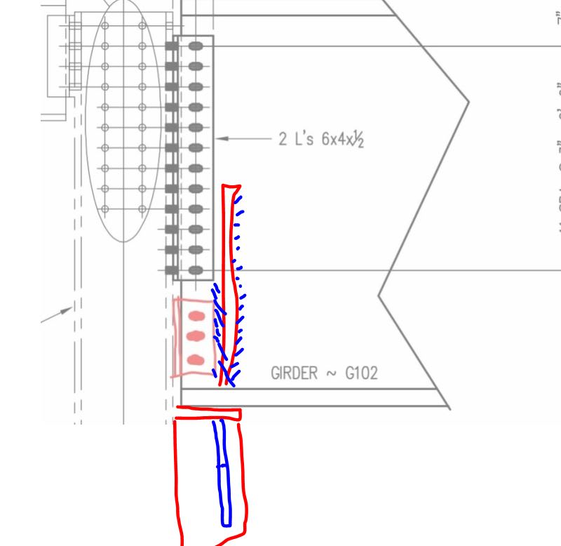
I have an existing girder that is getting an increased load. After analyzing the existing shear connection, I have found it to be 60k short (about 13% too low). I am wondering if there are any implications to adding another shear tab or double angle connection below the existing connection to take the additional 60k.

My gut is that adding another 3 rows of long slotted horizontal bolts in a double angle connection would work well. I think that rotation compatibility would still be okay since we are not engaging the flanges of the girder and there would be long slotted horizontal holes in the angles.

Screenshot_2024-10-17_114559_colime.jpg


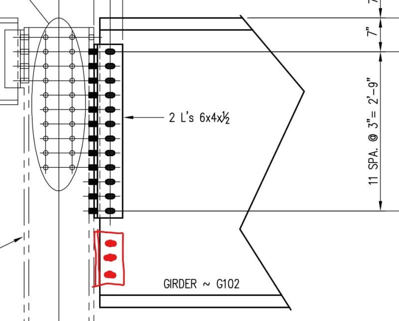
What are your thoughts?
 
Replies continue below

Recommended for you

Your strategy could work out just fine.

Depending on the governing limit-states and field-conditions, you might have alternate solutions available. For example: strengthening the conx by applying a pair of C-shaped field welds at the angle legs to the girder and abandoning the bolts in place.
 
I like your proposal and expect that most engineers would do the same.

That said, I do have some concern for load sharing:

1) The existing connection would need to deform a fair bit before fully engaging the lower connection I feel. Bolts are pretty good at redistribution though. And, really, this situation is pretty similar to what happens often with vertical bracing connections.

2) At the connections to the column, I'd not want to mix bolts and welds for fear that they would not deform compatibly and the welds would rupture. If possible, I would seek to use bolts for both conditions.
 
My Cadillac solution here would probably be a new bearing seat capable of handling all of the load on it own. That would be a heck of a seat though and may well intrude spatially in a way that would be non-starter. Beam stiffener install might be tough too.

c01_ep2azy.jpg
 
Are the bolts X or N? If they are N couldn't you redo the bolts to X? Or is that an on paper solution only?

I'm not convinced ADD-A-BOLT will take proportional load, we already know the top bolts tends to yield before the others and endures the most distortion....
 
My only concern is the additional movement required to activate the lower connection. However presumably, give then nature of limit state design that extra 13% the beam will likely never see. In fact the beam probably only sees 50% of the calculated loads. If that is the case then I'd be happy with things.

If the beam IS actually seeing regularly seeing high loads I'd opt for a better load sharing solution. Eg if the beam was carrying 80% dead load then and you really need good shear performance then I'd provide a connection that better shares the load.

KootK said:
1) The existing connection would need to deform a fair bit before fully engaging the lower connection I feel. Bolts are pretty good at redistribution though. And, really, this situation is pretty similar to what happens often with vertical bracing connections.
Agreed. But as commented above I'd avoid that unless the design loads are an unlike ULS (which in most designs is true.).
 
If the connection is already under decent load, then swapping the bolts out for higher grade bolts might be difficult if some deformation has already occured and they are jammed in shear.

What is the governing the failure mode currently? This may impact the strengthening chosen. And how much locked in load would the existing component be taking at the time you strengthen the connection? If theres only small locked in load then you won't have that many issues with load sharing between additional components.

You could investigate whether welding all around the L plates to both sides of the beam web would give you sufficient capacity, and design the weld to take the full load. Just need to be mindful if the connection is highly stressed in its current state if there are implications from heating it. If you are just supporting self weight of the beam for example, this is not usually an issue, but if you have got a fully loaded beam this might not be the best option.
 
I like DrZoidberWoop's suggestion. Weld the existing double angle connection to both the girder and column and design the welds to take the full load. If that doesn't give you enough strength, then add the additional angles per HDStructural's illustration (using welds). Leave the bolts in place, but don't rely on them for any strength.
 
lexpatrie said:
Are the bolts X or N?
Based on the load tables, swapping to X bolts will only add 5 kips or so, since the angle thickness starts to govern.

lexpatrie said:
I'm not convinced ADD-A-BOLT will take proportional load
I agree with you that adding one bolt, especially near its fully loaded state won't necessarily fix the problem. However, 80% of the load on this connection is a live load, so when the additional bolts (need 3 more rows, but will add 4 rows) are added only 20% of the total load will be applied. The remaining live load should adequately distribute to all of the bolts.

bones206 said:
Depending on the governing failure modes, you might be able to just swap out all the bolts with a higher grade.
That is a good thought, unfortunately I can only get a few more kips out of the connection until the angle controls over the bolts.

cliff234 said:
Weld the existing double angle connection to both the girder and column and design the welds to take the full load.
This would be a good solution but unfortunately the angles only have a little more capacity in them. So more angles will be required.

icebloom, I think my other responses cover your comments.

Thank you all for your input.
 
Are the existing bolts fully tensioned or snug-tight? If they are fully tensioned and the new bolts will also be fully tensioned, then there should be full sharing of load between the new and existing bolts, the same as if they were installed at the same time. That's assuming that there hasn't been any slipping of the connection previously, which should not have occurred under normal service level loading, but only if it had experienced design-level loading.
 
HDStructural said:
I agree with you that adding one bolt, especially near its fully loaded state won't necessarily fix the problem. However, 80% of the load on this connection is a live load, so when the additional bolts (need 3 more rows, but will add 4 rows) are added only 20% of the total load will be applied. The remaining live load should adequately distribute to all of the bolts.
If 80% of the load is live load then you are pretty well placed to just run with your solution and call it good.

If in the past the connection has experienced decent loads then the other bolts will likely have indented into the slots so the new bolts will lag behind the other bolts in sharing the load. However there is enough deformation in the system before failure that you can expect load sharing at ULS.
 
I really have my doubts there, Bridge.

As to the no slippage I'll refer you to the banging bolt phenomenon, that wasn't associated with "full" loading.

Back to the OP, what about butt welding the new angles to the existing so it forces the two angles to move together? In wood we could drive a shim between the two to force the nails to share the load more cooperatively...

I'd also be tempted to try to relieve the load some and maybe they could ream the holes through all three plies in the field so the bolts have good fit in the holes so they load share more tangibly. Smaller holes and no space between the bolt and the angle and web.
 
Back
Top