Continue to Site

Eng-Tips is the largest engineering community on the Internet

Intelligent Work Forums for Engineering Professionals

  • Congratulations KootK on being selected by the Eng-Tips community for having the most helpful posts in the forums last week. Way to Go!

INDUCTANCE OF A 3-CORE TRANSFORMER

Status
Not open for further replies.

Ethnan

Electrical
Mar 13, 2020
49
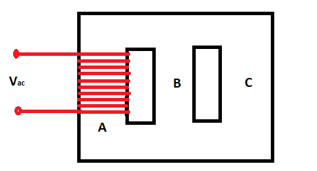
Parallel_inductance_o2nfab.png


What is the inductance of the coil?

I need to determine the current I, flowing through the coil. I=V/Z. Z is impedance of the coil.
Assuming the resistance of the coil is negligible compared to its reactance. Then I=V/X. X=2*pi*f*L where pi=3.142, f=50Hz. thus I=V/(2*pi*f*L)
Now, how do I find the inductance L of this kind of parallel circuit? Please assume that the reluctance of core A is Ra, and that of B and C are equal, Rb=Rc.
The cores have same cross-sectional area.

If you know the solution, please I would appreciate your solution.

Kind Regards
 
Replies continue below

Recommended for you

We don't do homework here and there is not enough information given to calculate your answer.

Bill
--------------------
Ohm's law
Not just a good idea;
It's the LAW!
 

Waros, this is not homework!

This is part of one of my projects. You can of course make any assumptions you need to make. The point is about calculating inductance of a parallel magnetic circuit, when only one of the cores have a coil around it. I already worked out a number of solutions, but need more experts to verify my solution. Thanks for reading through.

Kind Regards
 
I apologize. Have you noticed how the display may drop on the screen as a banner add loads? If that happens as you are clicking, you get the wrong link. I intended to look at your profile but inadvertently landed on the profile of a high school student.
To find the equivalent length of the magnetic circuit use the formula for resistors in series and in parallel.
You have three lengths to consider:
1. L[sub]a[/sub] The length of the "A" leg including the horizontal portions to the "B" leg. (C shaped)
2. L[sub]b[/sub] The length of the "B"leg. (I shaped)
3. L[sub]c[/sub] The length of the "C" leg including the horizontal portions to the "B" leg. (reversed C shaped)
For example assume the following dimensions:
Height = 2"
Width = 3"
L[sub]a[/sub] = 1.5" + 2" + 1.5"= 5"
L[sub]b[/sub] = 2"
L[sub]c[/sub] = 1.5" + 2" + 1.5"= 5"
The approximate effective length of the "B"+"C" combination is:
1/(1/5 + 1/2) = 1.43"
The total approximate equivalent length of the magnetic circuit is 5" + 1.43" = 6.43"
Use 6.43 inches to calculate the Amp turns per inch in this example.
For a closer approximation, use the center dimensions rather than the overall dimensions.[pre][/pre]


Bill
--------------------
Ohm's law
Not just a good idea;
It's the LAW!
 
waross said:
The approximate effective length of the "B"+"C" combination is:
1/(1/5 + 1/2) = 1.43"
The total approximate equivalent length of the magnetic circuit is 5" + 1.43" = 6.43"
Use 6.43 inches to calculate the Amp turns per inch in this example.
For a closer approximation, use the center dimensions rather than the overall dimensions.

Thanks so much for this. I got to this point. But the challenge for me is that cores B and C have the same magnetic permeability ,but different from the permeability of core A. Lets say their permeability is x times that of A. So I am thinking we cannot add the lengths 5" and 1.43" together just like that. We need to convert them to equivalent length of same permeability, my thoughts. I need it verified.

Kind Regards
 
What is your application? Someone may have direct experience, but your lack of details is discouraging.
Time and again, we field questions with general advice only to eventually learn that the poster neglected to share pertinent details, and the application is actually an exception or deviation from normal applications.

Bill
--------------------
Ohm's law
Not just a good idea;
It's the LAW!
 
Thanks Waros. I think I am good enough with your earlier inputs. More ideas came when I bounced ideas with many others.

For the learning, I had to convert all the lengths of different materials to their equivalent length of another material.

For example, the material with permeability of U[sub]x[/sub], Length L[sub]x[/sub], and cross sectional area A would have a reluctance of R=L[sub]x[/sub]/(A*U[sub]x[/sub]). The equivalent length L[sub]c[/sub] of the material of permeability U[sub]c[/sub] ,cross sectional area A , of same reluctance would be given by L[sub]c[/sub]/(A*U[sub]c[/sub])=L[sub]x[/sub]/(A*U[sub]x[/sub]). Solving, this gives you L[sub]c[/sub]=L[sub]x[/sub]*U[sub]c[/sub]/U[sub]x[/sub]. After converting all materials to the same material, you can now add them if in series, or do your parallel combination if in parallel.

Hope this makes sense for someone.
 
Thanks for the update.

Bill
--------------------
Ohm's law
Not just a good idea;
It's the LAW!
 
What transformer engineers normally do- calculate the per turn voltage of the winding. From this calculate the flux density in limb A using the formula e=4.44x AxBx frequency where e=per turn voltage in volts; A area of cross-section in m[sup]2[/sup] B- flux density in Tesla and f= Hz

Flux density in B &C limbs can be approx half in A.Take weight of limb A, B and C. Add weight of relevant yokes to weights of A and B+C. For the type of material and particular flux density, there are published exciting kVA / KG graphs for different B. From this, you get the total exciting kVA required. Add a building factor (1.1-1.2) to take care of the joint design, building stress, etc. From this, you can calculate the exciting current. Once you know V& I, find out X and L from it.
 
Status
Not open for further replies.

Part and Inventory Search

Sponsor