Eng-Tips is the largest engineering community on the Internet

Intelligent Work Forums for Engineering Professionals

Inductance of ferrite core inductor at low B field

Status
Not open for further replies.

cavitate

Civil/Environmental
Aug 12, 2008
53
0
0
US
A bit of back story for context. 45 years ago in an electronics class, the instructor passed out heavy duty, 5 Henry audio Chokes to the class members, We were all told to find the inductance.
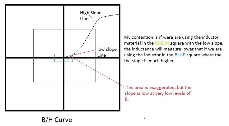
We did, and the general consensus was answer was it was a few milliHenries. And we were on to the next assignment, there was no discussion about why we had the millihenries instead of Henries. This got me started on finding an answer answer and I ended up learning about B/H curves. The answer I ended up with is that our measurement current was so small that the H field line slope was still very shallow (10*). It wasn't until you got to much higher H field (more current flow) that the slope got up to say 45* instead of 10*. An exaggerated drawing to help explain. i.e. if you look at a B/H curve, at the very beginning the slope is very low, but as H increases the slope increases. And, in my mind the inductance is higher.
B-H_Slope_Curve_Question_h1ci4g.jpg


First let me know if I misunderstand how slope of B affects inductance.

Now, assuming my thinking is correct, this is my question.
I'm winding transformers for RF antennas where signal strength is measured in uV and the equipment used to test these transformers is in millivolts. So, are we getting a true measurement of the primary and secondary inductances? I'm thinking a low signal levels inductance would be much lower.
Another thing I factor in, commercial receivers have very tiny transformers on the input (OD 3/16" or less), I think this puts the B higher on the curve even at low RF voltages. My latest need is a 9 to 1 impeadance transformation, I can use a 0.5" OD core or a tiny Minicircuits transformer, now I wonder if the minicircuits will be better at the low uV signal levels.
Please share your thoughts on this topic.
Thanks, Mikek
PS, after writing my question I did find this video with a good B/H graph of the low level non-linearity at the 5:00 mark. Also the domains shown before and at saturation, made me think, that it takes a certain amount of energy to move the domains, at low levels we may not be moving many are any thus low inductance.
 
Replies continue below

Recommended for you

I have wound 100s of transformers, they all work, but as they say fray the end of a coax and you will receive may signals,
But does that make it a good antenna?

Mikek
 
I'm setup with two fiberglass poles 70ft apart, the original plan was for a DKAZ antenna, but heard it had low output on LW signals so decided to start with a Superloop antenna with a variable termination, and then later switch it over to a DKAZ. I later got info that the DKAZ is OK on LW, but needs an amp which I have.

Superloop, DKAZ
I plan to experiment, comparing a 9 to 1 transformer, to a Dallas Lankford 2 FET amp,
compared to a 2 FET amp driving a noiseless feedback 12db gain amp.
I'm also working on a wireless remote control variable termination.

But, I'm still wondering about the B/H curve dilemma I have wondered about for way to many years.
Next, I'll be asking about measuring impedance ratio with large attenuation inserted in the measurement.
After 45 years, I wish I would have learned more!
Thanks, Mikek
 
> Remember, now you have the opportunity to learn more!

LOL, I'm plenty aware of single turn untuned loops, multiturn Tuned loops, BOG antennas,
Yagi's, Phased antennas, etc. But sure, I'm always learning new things.

>You're planning a FET preamp, why not just a 1:1 transformer for isolation

The Super loop with a termination resistor has an output impedance of Approximately 900 Ω,
making a 1:1 transformer the wrong choice for matching the the antenna to the feedline.
And before you tell me a 9:1 transformer is wrong to match 900Ω to a 50Ω feedline, I'm not using
a 50Ω feedline, I use Cat5 cable with about 100 Ω characteristic impedance. I have found it better
at reducing feedline pickup which distorts the desirable antenna pattern.

Now, matching the antenna with a 9:1 transformer reduces the output voltage by the stepdown ratio.
In this case we have a 9.5db voltage loss. Also when you match an antenna to it's characteristic impedance
the output voltage drops by 1/2, that is is another 6db of voltage loss. The 2 FET amp has a gain of 1.
However, it has a high input impedance and a 100Ω output impedance. This unloads the antenna and matches the feedline
and doesn't create the 6db voltage loss of a matched antenna. Over all, the 2 FET amp has about 15db voltage gain over the 9:1 transformer.
I'm building the impedance transformation box in such a way that I can compare 3 different matching and gain scenarios.

>You need not worry about the B-H characteristics, unless you're dealing with high currents and saturating the core.

So, in you're opinion, very low signal levels in ferrite material will flip the domains just as well as large signals and
maintain the same inductance no matter what the signal levels are, (as long as it is not in saturation).
We just disagree.
Do we have any agreement that ferrite materials are non-linear?

>In that case you use air core transformers anyway.

Air core transformers become very difficult (being generous) if not impossible at MW and LW frequencies.

Thanks for your input,
Mikek

 
Also, rereading, I see you wrote,

>So try 36 primary to 4 secondary turns

A 9:1 impedance ratio transformation, requires a 3:1 turns ratio.
So far I have wound a 5 to 15 turn transformer, the primary inductance is about 20% high.
I will try a 4 to 12 turn ratio today, I suspect I will have to give a little on the low end
frequency response, for the lower turns count.

Mikek
 
I thought of another way to phrase my question.
At what signal level is AsubL measured?
Does AsubL decrease at very low signal levels?

Thanks, Mikek
 
Rotational dynamics dominate ferrite response. Domains are more common in ferromagnetic materials.

You have to explain your term AsubL


>You have to explain your term AsubL
I will, but why are you telling me how to wind a transformer when you don't know what AsubL is?

AsubL is a characteristic term of magnetic cores, It is a combination of physical size and the permeability of the magnetic material.
It is used in the calculation of the turns required to wind a proper transformer. Each core has a specific AsubL that can range from 2 to 18,000 or more.
When you design a transformer, in my case an RF transformer, you start with the impedance ratio. Say 900Ω to 100Ω, that is
a 9 to 1 ratio. The formula Zp/Zs = (Np/Ns)^2 is used to calculate the turns ratio. Z is impedance, N is number of turns, p is for primary and s is for secondary.
Rearranging with a little algebra, the square root of 900/100 = 3 = Np/Ns, thus the turns ratio is 3 to 1.
Then, you have to find the lowest frequency you want your transformer to operate at. In my case 200kHz (for LW reception). In order for a transformer to properly transform impedances, the impedance of say the the lowest impedance winding at the lowest frequency of use, needs to be 4 times the impedance that winding will see. A 100Ω winding should measure 400Ω impedance at my chosen 200kHz.
So, 100Ω winding at 200kHz is 80uh, multiply that by 4 and and you get the minimum inductance of the 100Ω winding, 320uH. Now the ferrite binocular core I'm using has an AsubL of 12,000. The formula is N=1000 * sqrt of (desired 'L'(mH) / AsubL(mH/1000turns) So converting 320uh to mH we get 0.32mH.
Then crunching the numbers, 1000 * sqrt (.32/12000) = 1000 * sqrt 0.0000267 = 1000 * 0.00516 = 5.16 turns well we can't do partial turns so I rounded down to 5 turns. The turns ratio is 3 to 1 so we have a 5 to 15 turn transformer. If you follow through and do the calculations for the 900Ω winding, you will see it also has 4 times the impedance at 200kHz. You can calculate either winding and the turns ratio makes the other one have the proper needed impedance.
I spent the last 30 minutes looking for a tutorial that would make it easier to follow than what I just wrote, but I didn't find one, video or text.
There is much more calculation that can be done to stay below saturation and to keep the temperature low, but at these low levels that's not a concern.
Mikek
 
>Glad to have helped you clarify your problem, as your post was quite ambiguous.

LOL, my explaining to you about the use of AsubL in transformer calculations did nothing clarify anything in my original post.
I'm sorry, you didn't understand, but, rather than my question being ambiguous, it was just above your level of understanding.
To put it in the most simple terms for you, I want to know about the non-linearity of ferrite materials, specifically at low flux density.

You can probably glean some info from this site.

Also this Magnetics catalog contains data about ferrite toroids, pages 16 thru 22 specifically list
the sizes and materials, L, R, P, F, J, W, and C and at the top the AsubL (AL) of each.

I'm surprised I could not find one document or video showing how to design a simple impedance matching RF transformer.
May be that is a hint that I need to make one. If you find one that helps you understand, please post it.
I learned about winding transformers in the ARRL Handbook, that was 35 years ago, I hope they still have it in the latest editions.
This is where I picked up the 4X guide on the needed inductance of a winding. I never understood where the number came from until I found a graph online showing how if ypu get below 4 the normalized impedance drops of and the phase angle goes up.
The "Practical RF Design Manual" by Doug Demaw has a section about the calculations.
Mikek
I did wind a 4 turn primary and the inductance was to low to make a useful transformer, so, it's 5 and 15 turns on my transformer.
 
Status
Not open for further replies.
Back
Top