Continue to Site

Eng-Tips is the largest engineering community on the Internet

Intelligent Work Forums for Engineering Professionals

  • Congratulations KootK on being selected by the Eng-Tips community for having the most helpful posts in the forums last week. Way to Go!

Industrial Hydrogen electrolysers - Crazy bolting systems... 2

Status
Not open for further replies.

A8yssUK

Industrial
Apr 7, 2014
42
Hello everybody,

I want to ask about the bolting on industrial hydrogen electrolysers.
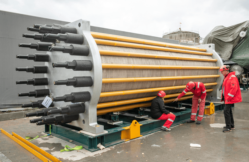
These systems can have 150+ cells bolted together with a single bolting system, to create a stack.
Each cell of the stack are sealed with a gasket of some sort. EPDM, Viton, PTFE etc..
Generally a low internal pressure is present say max 1 bar, and temps upto 90°C.

Example image of an industrial stack, check out the crazy bolting!
Skjermbilde_ijzdxs.png


Now normal calculations for a bolted flange joint are for single gasket systems.
How valid is it to use these calculations with a stack of 150 gaskets..
What additional assumptions are we making when stacking 150 of them together.. i.e. does the stress really translate evenly through the whole stack ?
Then how on earth do you load this evenly, many people fail to load a single gasket system correctly!
What about flange/fastener bending ? and such long bolts what about thermal length changes ???
How does a slight gasket and/or bolt hole misalignment effect the entire stack ?
Many systems I've also seen use a crazy amount of spring washers (40+)... to maintain loading forces with material creep etc..
Do the normal calculations for spring washers also start breaking down ?.. surely losses from things like friction etc start becoming major factors when stacking so many together.

I am trying to create a list of additional considerations compared to a single gasket bolted system.. can anybody else think of some or have any additional thoughts?

Thanks in advance for any input!
 
Replies continue below

Recommended for you

Hi A8yssUK

To me all I would do is consider the elasticity and stiffness of the two materials similar to that if you were bolting two metals together. That said I see a problem if the stacks are mounted vertically then the gasket at the bottom or base would also be subjected to the mass of all the segments above it, if the stack is horizontal then the gaskets see only the preload.

I guess to achieve an even bolt load on each rod one would need to do hydraulic bolt tensioning and the photo you posted appears to reflect that.

“Do not worry about your problems with mathematics, I assure you mine are far greater.” Albert Einstein
 
Assemblies this large are typically sealed using formed seals in an assembly that bottoms - ie seal pressure is not taking the normal force from the tension ties holding it all together. This is done to eliminate the huge elastic stack you'd have to otherwise deal with.
 
If it does have elastic stack like a plate and frame heat exchanger then it's common to specify a face to face distance between the flanges to give proper compression.
 
desertfox said:
That said I see a problem if the stacks are mounted vertically then the gasket at the bottom or base would also be subjected to the mass of all the segments above it

I haven't done the calcs but I would guess the additional gravity load would be insignificant when compared to the total preload. Am I wrong in thinking this?
 
Hi Kingnero

You might well be correct, I have no idea what the thing weighs or whether it’s horizontal or vertical in service, without some input from the OP we won’t know👍

“Do not worry about your problems with mathematics, I assure you mine are far greater.” Albert Einstein
 
I have seen these assembled.
Hydraulic tensioning and working very carefully.
The analysis has to include the stiffness of each part, the compression properties, and thermal expansion.
The ones that I saw had no springs in it.

= = = = = = = = = = = = = = = = = = = =
P.E. Metallurgy, consulting work welcomed
 
Large stacks like this are mounted horizontally. Look at the end rings, notice the large feet. Not just for shipping.

Every vertical 'ring' in the round section is an individual electrolysis cell. Efficiency of the process is driven by very fine pressure control in the liquid flow in and gaseous flow out of each cell which is more difficult the taller the stack is. It's also important that voltage and pressure conditions are as balanced as possible across every cell in a stack. If they were oriented vertically, pressure balancing every cell would be complicated (they're controlling pressures to a fine enough level that head differential between adjacent sections of the stack would be a problem).
 
Hi all thank you for the replies,
I have seen these stacks both horizontally and vertically mounted... generally the vertical ones are smaller, probably for the reasons SwinnyGG gives above.

@kingnero is also basically correct the weight of the end plates pales in significance to the power of the (bolt) force. *Vader breaths* .
When tensioning the bolts nice and evenly with decent CALIBRATED hydraulic tensioners your looking at a minimum +/- 10% swing in the applied bolt force per bolt due to a whole catalogue of things (mainly bolt/nut defects).. so if each bolt has a 10% spread on force, how does this unevenness translate through the 100+ stacks...I assume stiffness of the cells etc all play a role of how the force gets distributed down the stack.. I also assume the middle of the stack somehow sees the least force... but by how much and how is it distributed now ?

@SwinnyGG form in place sealants (FIP) can contain components/contaminates which can damage components in the electrolysis cells over time and bottoming out the connections instead of having them "floating" on the seals can cause mechanical issues vs things like vibrations and thermal expansions etc.. best to let the seals take the loads/changes*. FIP seals proved decent enough in the first/2nd generations of these cells types but to get better reliability users are looking at other options. I work for a company specializing in PTFE compression seals, we can give this reliability I am sure of it, but loading the devices up and keeping them floating during ultra long service intervals is now the challenge. Which can be done with careful design, however I am sure extra calculations are required when using 40 spring washers compared to using say just 4..

*seriously if somebody chimes in that spiral wound gaskets are best being fully compressed against the metal support rings...I don't have time to argue with you.. but you are wrong :p
 
A8yssUK said:
form in place sealants (FIP) can contain............

Ive never seen a wafer stack like this use wet sealants. I said formed seals - ie o rings - not formed in place sealants. I didn't just say 'o rings' because the ones I've seen did not necessarily use a simple round cross section for the wafer seals - some did, some were more intricate geometry.

Every wafer stack like this I've ever seen used a fully encapsulated formed seal between wafers. While this is for an electolyzer, gas filter stacks in gasification/waste to energy plants are mechanically very similar, and the ones I've seen use very similar sealing solutions.

Thermal expansion is typically handled by tension retaining devices in the heads. It can be a concern when process equipment is outside, but in my experience that's rare. These devices are designed for very long uptimes; once they're up to temperature they tend to stay there for a long time until service is required. As a result, thermal expansion of components in the stack is accounted for in the design stage so that when the stack is assembled, the level of applied tension on the stack is tolerant of the growth between cold start up and long term steady-state operation.
 
@swinnyGG Apologies I know these types as preformed gaskets, generally made from elastomers such as FKM, NBR, EPDM and Viton etc.. However these can also contain contaminates from processing which can damage the anodes/cathodes of the cells, albeit generally in lower concentrations than FIP style gaskets. You also get PTFE/FEP encapsulated variations.. which are awkward and you can never 100% encapsulate anything perfectly every time.

As these devices will be often used for H2 production supplied from green power generation technologies (wind, solar etc) they are required to react to demand, so admittingly I've assumed this will also mean temperature fluctuations in service...but perhaps they use methods to keep the temperature stable. I have also only seen them housed inside... so lets say a temp range of -10°C - 100°C

Having talked with a few FEA engineers in my company, this setup would be difficult to simulate in a meaningful way; but not impossible. I fear too many assumptions would be required to do it justice.

I'll look into performing good old lab scale replications... but do not look forward to cutting and installing 100+ gaskets for each experiment :)
 
Just as another reference point, google search "plate pack" heat exchangers. They use the same principle, but are normally rectangular, not circular. Ultimately, I think you'll find that they are an evolution of trial and error (i.e. physical testing), backed up by a calculation or two along the way. So your plan on garage scale models is pretty much how these things would have been developed over time.


Andrew O'Neill
Specialist Mechanical Engineer
Australia
 
A8yssUK said:
but do not look forward to cutting and installing 100+ gaskets for each experiment

I think you'd likely have good luck just welding up continuous o-ring seals yourself from commercially available stock. It's what I'd do if I was trying to build something like this by hand.

Your concern about contamination from the gasket/seal material is valid; in commercial application they use high purity materials which are hideously expensive. For a self build I don't think the performance penalty from standard materials of reasonable quality would be noticeable.
 
@SwinnyGG A home build???... no this will be done in a professional laboratory... just a simple setup with regards to testing the sealing capability and not electrical output or anything, probably pressurize with helium and use a sniffer so I don't explode the lab (again!).
The H2 electrolysis cells are apparently very touchy with contaminates and we are also getting reports of crevice corrosion occurrences near the seals, even with the pricey rubber materials.. I know expanded PTFE seals can help here... and they are in roughly the same price range if they are even attempting the high end rubbers.
 
Status
Not open for further replies.

Part and Inventory Search

Sponsor