Continue to Site

Eng-Tips is the largest engineering community on the Internet

Intelligent Work Forums for Engineering Professionals

  • Congratulations GregLocock on being selected by the Eng-Tips community for having the most helpful posts in the forums last week. Way to Go!

Inelastic behavior of Tension Clips/Fittings

Status
Not open for further replies.

VN1981

Aerospace
Sep 29, 2015
186
Recently, we had to analyze a Tension T-Fitting for a client and we were getting negative margins at DLL. The client suggested that we could use plastic bending allowable instead of Fty and show it good. We performed the calc and it got me thinking.

How would be the behavior of a fitting/structure which has undergone some plastic deformation.

Consider a typical L-Clip. Mostly, the peak stresses will be in the bent/radius region of the clip. Lets say that the peak stress value is beyond Fty and the clip has some permanent strain in the bent region.
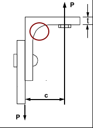
tclip_qol82h.png


1. Has the stiffness (Modulus) softened in the circled region due to permanent strain?

2. If further loading is below DLL (say 0.75 of DLL) in the clip, how does the clip, especially the circled region behave? What would be the stress values in the above region?

Would like to get a better understanding of the physics.
 
Replies continue below

Recommended for you

This is a subject of study in many of the major aircraft OEM design guides. Though they sometimes copy each other unashamedly, the values don't always agree. They're usually limited in the number of materials/tempers covered.

Some "settling" of structures after assembly is expected. But this sounds like a different case. Many other questions come to mind. What would be the relaxed state of the structure after this DLL is applied? Do you expect the angle to remain opened up by several degrees or a fraction of a degree? How far into plastic strain does the angle go? Is this an extruded angle, or a machined part... which way did the cutter pass if it's machined... and the grain direction, too, if it's machined... gets worse pretty quickly... What surface protection is present? Is the surface exposed to the atmosphere, fuel, corrosives, or, worst of all... passengers' spilled drinks? Will gaps open in the other joints as this angle is pried open, and will they completely close when the limit load is relaxed?

The linear Young's modulus will remain the same after plastic deformation, but the yield point will change after your limit load cold-works it (depends on the material) and then there could be a new tangent modulus at play. Venturing into plastic deformation while the structure is experiencing limit load, or less, is asking for other consequences such as warping or buckling of the structures to which it is attached: now that one part has changed shape permanently, all parts will relax to a new position once the load is removed. Perhaps not consequential in some secondary/tertiary structures, or it could set up the adjacent sheet metal for premature bending/compressive buckling, now that there's a new couple applied to the end.

Basically, even if you can make a static load analysis pass, it sounds like this could easily set up a long-term life problem, either fatigue or stress-corrosion-cracking depending on the part, the load, and the environment. And that's why, as I mentioned earlier, that the OEM's have the design curves in their manuals: they spend way too much money fixing this kind of stuff after the planes go flying.

STF
 
exceeding yield for DLL should be viewed with suspicion. using plastic bending to "show it good" doesn't fill me with confidence. and, yes, i know the rule says "significant" plasticity; yes, i know every single hole in the airplane has some plasticity at limit.

if you're doing analysis for someone else's parts ... use standard industry practice, and show it "not good". if you're on the hook for the analysis, and you "show it good", and later the guy signing it off (or the lawyer after the crash) says "hello, hello, hello ... what's all this now" and you're in the crapper ... even if you have a trail that says the customer wanted you to do it this way.

if your analysis, shows it down, consider a test.

if you're using the McCombs curves (like from the supplement to Bruhn), know these are very conservative ... i tested one angle and we ran out of load (at double the required) and no sign of distress.

another day in paradise, or is paradise one day closer ?
 
Generally speaking the 'L-clip' shown is a 'shear only' type member, that would only have a very light [low] tension rating.

The problem with this 'simple design'... most likely from extrusion or machined angle from a bar.... is that it will have substantial fatigue cracking potential... and really poor [single-row] fastener loading... especially in the 'shear flange' [complex shear and tensile loading].

IF the angle was modified to have a thicker tension flange and a wide [tapered!] shear flange [for multiple fastener rows] with a very generous fillet radius between flanges [bolt may require a shim-washer with edge chamfered to nest in the fillet], then it MIGHT be capable of moderate cyclic tensile loading, as shown.

Better, yet, IF this "L-clip" was machined [with flange/fillet modifications that I noted in previous paragraph] from forged bar and had 'stout' integral stiffeners between the flanges [to grossly reduce stresses in the fillet radii], spanning around fastener holes, then significant cyclic tension loading would be possible and demonstrable. In effect, this machined clip would be like a mini-bathtub fitting.

Regards, Wil Taylor

o Trust - But Verify!
o We believe to be true what we prefer to be true. [Unknown]
o For those who believe, no proof is required; for those who cannot believe, no proof is possible. [variation,Stuart Chase]
o Unfortunately, in science what You 'believe' is irrelevant. ["Orion"]
o Learn the rules like a pro, so you can b
 
As well as all the design and stress analysis sometimes it is just as easy to refine the load analysis to get a part to pass.

For this I would have pulled the mill cert for the material used and established the actual Fty, if it was sufficient concession that installation & fix the design.

The other point would be where is the clip, if the design loads are much higher than actual service loads (FAR 23 flight loads, emergency landing loads, role equipment) then there is approach is likely to have little impact but if the actual service loads are a large percentage of limit loads say pressurized skin then NO way. The other consideration is, it is effectively a soft joint, will the load follow another path and what is the effect (will it case cracking in a folded flange or working skin rivets, etc).

Noted: edited the excessive use of "ed" in 2nd paragragh.
 
well my 2c ... I would certainly not do that (use the specific material props of the detail part to show it good) ... unless I added that testing as a note on the drwg, including a minimum required, so that the testing is repeated if the drwg is reused.

I suspect that your analysis is conservative, and I'd test if it doesn't show good.

another day in paradise, or is paradise one day closer ?
 
Thanks folks for the replies.

Fortunately, this analysis will be reviewed by an OEM appointed signatory & he will be putting his name on the document. Also the guidance of using Plastic bending allowable came through him.

The part is a bracket in a lower panel on the AFT part of the wing. The bracket is connected to a strut rod which in turn is connected to the gear beam. The arrangement b/w bracket & strut rod is via lug type.

The bracket is fastened to the panel using a fastener group. I realize the description may be vague but this is as best/far as I can go without comprising the NDA terms.

We only have the lug pin load definitions supplied by the client. The rod carries both tensile & compressive and thus a tension T-fitting analysis.

The tool used for the analysis is from a major OEM and is highly validated. It is the method to mitigate negative MS, is what sparking the question.

The brackets are of different Al alloys mainly 7000 & 2000 series.
 
Well maybe you can wash your hands of this one.
Beware of being asked to pull the same rabbit out of your own hat, some time in the future.

Going to the mill-certificate for strength allowables only works if you make the bracket once, and test it enough to validate the data from the mill. This sounds like on-going production, though.

Is a test feasible in this case? (you didn't mention one) The majority opinion here is that testing can pass the part when the analysis shows negative MS. This is fairly common and there are many times when the typical analysis is known to be conservative. Was thickening the part an option that was considered? We understand how you may be limited in what you can say, but the "what-if" stuff isn't likely covered by non-disclosure agreements.

STF
 
Status
Not open for further replies.

Part and Inventory Search

Sponsor