Eng-Tips is the largest engineering community on the Internet

Intelligent Work Forums for Engineering Professionals

Injection lances design for Big diameter 7

Status
Not open for further replies.

Carreroal

Mechanical
Jan 27, 2020
6
0
0
ES
Hi everyone, I working in a injection chemical process for entrance of RO system, and the principal Pipe of feed system have 2600 mm of diameter. We have a proposal for material. We think in teflon for all the body of this injector with 30ª of inclination respect to the vetical.

Any of you have experience about materials and injectors for big diamenters? (1.8 m/s fluid velocity)

Thanks in advantage.
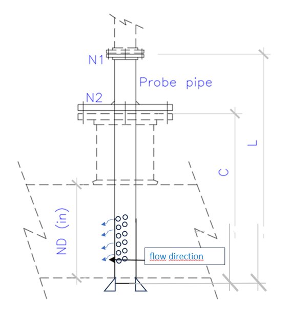
Injector_1_zh39pi.png

Regards

Ander
 
Replies continue below

Recommended for you

The typical material of the injector in the RO system may use the 300SS series similar to the RO piping or a suitable alloy depending on the type of chemical.
 
Why not to buy this device from a manufacturer? Why do you want to develop a proprietary design? Why injection, why not a static mixer?
 
Having experienced the design challenge and expense of a 42" NPS static mixer I wouldn't wish a 2600 mm/102" diameter static mixer on my worst enemy.
 
Hi,
Who talk about using a 102" diameter static mixer? The function is to mix the chemical with water in a certain ratio before introduction in the system.
Pierre
 
Actually, the new real DN2400 and this big size is cause it's the main seawater feeder. Is the first inyection poit of chemical and it's necessary for specific requerement. Traditional static mixer (with internals)would be expensive...
 
pierreick said:
Who talk about using a 102" diameter static mixer? The function is to mix the chemical with water in a certain ratio before introduction in the system.
OP has a 2600mm DN2400/96 NPS seawater pipe to inject a chemical into. How else would a static mixer be implemented other than as a full diameter inline component?
 
In large diameters these are often sets of partial baffles to cause turbulent mixing.
This will take a fairly long distance to accomplish.
Injecting the chemicals is the easy part, getting it all well mixed and reacted is the hard part.
The injection system must resist corrosion at all concentrations of the injected chemicals.
If this is seawater you are not using common SS.
What is the material of construction and what is being injected?

= = = = = = = = = = = = = = = = = = = =
P.E. Metallurgy, consulting work welcomed
 
The material es GRP and chemical injectios is the classical for RO process (SB, FC); and we considered units in parallel for space reassons
 
I bet that degree of mixing will be inaceptable and (1) large portion of membranes will be unaffected by treatment (~30%) and (2) large portion of chemicals will be consumed as a wasting of money (~50%). Flaws of such design are rather obvious.
Optimum mixing is always a challenging issue if one does not want just to submit positive reports about money&resources spent and does care of actual results.

Still curious what reason this installation needs PTFE and proprietary design.
 
Good mixing will be more difficult at low flow - low Reynolds number, so what is the min operating flow here ?
At 30e3 m3/hr, Reynolds number is 5.5e6 - turbulent flow regime.

Check with instrument engineers who know a thing or 2 about vortex shedding around long thermowells and the min required thermowell thickness to withstand resulting forces on this injection quill. Have my doubts if a 90-96inch teflon quill has the structural strength for this service.

Talk to these folks also; description says they have installed inline mixers on lines up to 2200mm dia:

 
To echo georgeverghese's concerns. Do check wake frequency calcs. If you do not have instrument engineers at your firm, apply ASME PTC 19.3 TW. It's an easy standard to work through that will give you a solid design basis along with known safety factors, you know, "CYA". I have seen injection quills fail and the most common cause was as noted above, incorrect wall thickness i.e. mass or incorrect material selection i.e. strength and elastic modulus.
 
¡Thanks you so much georgeverghese and Heaviside1925 for this nice information!. Reynold's number for this case is as follow:

Raw data: flow velocity3 m/s,
pipe diameter: 2400 mm,
kinematic viscosity: 1 ×10⁻⁶ m2/s (aprox)
Result: Reynolds Number Re=7200000
Flow type - turbulent

A material options for the injector is teflon because have a good results hardness a ductility charactericts to support bounding in other similar practices.
 
Strength and ductility are great all up until its flopping around like a shillelagh inside your pipe when it hits resonance. I wish this phenomenon was more widely taught to mechanicals because in my experience instrument engineers know this check inside and out for thermowells, but injection quills seem to land in mechanicals lap. If you would like to check your wake frequency calcs, there are some good spreadsheets you can download from thermowell manufactures websites where you input your material, process, dimensional data and it gives you a pass or fail based on the code I referenced. Make sure you check all possible variables for the process stream such as flow rates. Again, I am telling you this as a CYA. I thought there was at least one pipe flow program and I think some structural programs that have an option to check this as well, but I don't recall which ones they were and maybe a ChemE or SE could point you to it if you needed something more official than a vendor's spreadsheet and you don't want to do hand calcs.
 
Status
Not open for further replies.
Back
Top