Continue to Site

Eng-Tips is the largest engineering community on the Internet

Intelligent Work Forums for Engineering Professionals

  • Congratulations MintJulep on being selected by the Eng-Tips community for having the most helpful posts in the forums last week. Way to Go!

Inlet Filter Pressure Losses 1

r.borghino

Structural
Nov 25, 2024
10
Structural engineer here, trying to figure out if the equipment in a small warehouse is appropriate. I own it and want to avoid retrofitting the ventilation. Looking through the data sheets they gave me, and running some basic numbers, the areas and air volume (CFM) through the inlets and outlets seem to match, but the inlet calculation does not include the filter pressure drop so I'm questioning the real air volume through the system to ensure 3 ach.
I have one outlet with an exhaust fan, which has a rated "Static Pressure" of 0.41 inH2O for the air volume (34k CFM) needed.
I have two inlets. Each is an assembly of a louver with a 1" filter. Each louver is 90" x 60", and has 12 filter panels installed to cover the louver area. The louver (without filter) has a rated "Pressure Drop" at the needed CFM of 0.09 inH2O. However, each filter panel (20"x20") reports a "Resistance" of 0.035 inH2O.
No ductwork. Just two inlets into a large rectangular room and one outlet.

So.... I was hoping any of you would be able to point me in the right direction. My instinct was just to add the Louver and filter pressures, add that to the fan's pressure and get the new(real) CFM from the fan curve... but since these pressures are all called different (Static Pressure, Pressure Drop, Resistance) I don't know what to make of it.
 
Replies continue below

Recommended for you

So are you saying that the required flow to achieve 3 ACH is 34,000 CFM which is the design output of the fan at 0.41 inches wg?

If so then based on what you say about the system configuration and pressure drop, there is only a total of 0.125 in. wg. pressure drop across the inlet with clean filters and basically no pressure drop across the outlet without any ductwork on the exhaust fan. But I am not sure if any other components in the air stream of the exhaust fan which may cause pressure drop such as exhaust louvers, dampers, etc.

Therefore there is about 0.276 in. wg. extra in the fans pressure output capabilities allowed for dirty filters. Seems reasonable. Why do you think the system may be undersized? Are you having any issues?

What will happen if this is all correct is that with clean filters the fan will operate on the point of the fan curve at a higher flowrate than 34,000 CFM at a system pressure drop somewhere between 0.125 and 0.41 in. wg. with clean filters (operating point will "run down the fan curve"), and with dirty filters will operated closer to 34,000 CFM at 0.41 in. wg. With really dirty filters the pressure drop will be greater than 0.41 in. wg. and the flow will be reduced below 34,000 CFM.
 
Last edited:
As an engineer I have to admire how concise and informative to the original question that this last post is.
 
See the following link for how your fan performance will change depending on your system's characteristics: https://integracontrols.com/fan-curves-explained/

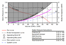
Please see the below image for an illustration of what Snickster wrote.
This was very useful.
I understand the general principle, basically, for my fan there would be a new system curve that includes the filters. The screenshot is the real curve for my fan and the purple line is what a new line might look like. I am concerned that it is under-designed.

Is there a way to estimate the new system curve that includes the filters?

Thanks!
Screenshot 2025-01-15 at 7.59.10 p.m..png
 
Is this the original static pressure calculations that you found somewhere?

If so what I understand is that the exhaust fan is in a wall housing and includes a backdraft damper and weatherhood on the discharge which static pressure drops are listed in the tables. External static pressure of 0.15 appears to be the static pressure drop across the inlet including louver and filter as external static pressure refers to pressure loss across items external to the fan unit. Therefore this pressure loss appears to account for the louver 0.09" wg plus clean filter 0.035" wg you previous indicated in your original post. Therefore this will be the operating point - 0.42 in. wg at 35,000 cfm - as shown by "System Curve" blue dash with clean filter.

The purple curve you show is actually about where you want to limit the operation of the fan since any less flow will be in the "do not operate" shaded area. This crosses the curve at about 0.55 in wg at 30,000 CFM so you have about 0.13 inches wg available for dirty filter which seems about right. But if the flow slows down to 30K the 0.42 drop across other items also falls in accordance with the square of the flow so the result is the flow with dirty filter will be a little higher than 30K assuming about 0.13 to 0.15 in. wg extra loss with dirty filter.
 
Is this the original static pressure calculations that you found somewhere?
yep these are the original ones. Ah.. I see the External SP values I didn't know what that was relating to... so yes, looks like it's all good. Thanks!
 
If the system is existing just go on Amazon and buy a $15 anemometer and measure the airflow. If you have one outlet measure the feet per minute discharge velocity. Then multiply by the duct area in square feet to determine the actual CFM.
 

Part and Inventory Search

Sponsor