Eng-Tips is the largest engineering community on the Internet

Intelligent Work Forums for Engineering Professionals

Inspection of reliefs and chamfers

Status
Not open for further replies.

CTengIS

Mechanical
Jul 25, 2023
30
0
0
IL
Hi all.
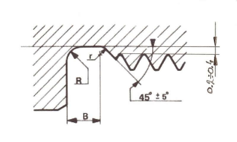
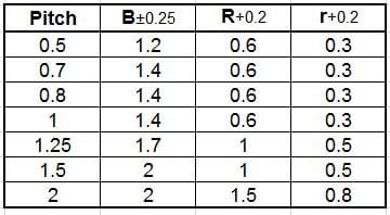
Please refer to the images below showing dimensions and a tolerance table for a relief geometry at the end of an internal or external thread.
I have two general questions:
1. What are some common measurement means to inspect these requirements (distances and angles with tolerances), on an outside (threaded shaft), and inside (threaded hole) areas of a mechanical component?
2. If the dimensions were changed to "basic dimensions" and the requirements were given as a profile of a surface geometric tolerance, would that force a change in the measurement methods, and would it make inspection easier or more difficult and costly, for the internal and external cases?
Thanks in advance.

ThreadeningReliefe_yquflf.jpg


ThreadeningReliefeTable_alj461.jpg
 
Replies continue below

Recommended for you

Externally, an optical comparator works great. Internally you can use a casting material, such as Repro-rubber, or section one part. We will sometimes qualify the (form) tool used.
 
Qcprick63,
Thank you for the valuable input.
Am I assuming correctly that in the case of internal geometry, once the casting is ready or if the form tool is qualified, the inspection will also be performed on the optical comparator?
Also, if the specification changed to basic dimensions and profile tolerances, would this complicate the inspection, or maybe the the other way around, make it easier (for example, once an overlay is ready for the comparator, you can use it to inspect all features at once, not having to measure each dimension separately)?
 
Unfortunately, the optical comparator cannot inspect the form on the I.D. A Profile call-out would make the inspection almost impossible, and very time consuming. Perhaps a functional test plug would be a good alternative? This is a fairly common construction, maybe someone else could offer their solutions?
 
Qcprick63, Thank you again, but if I may ask you for additional clarification:
Once you make the casting of the internal geometry ("Internally you can use a casting material, such as Repro-rubber") don't you measure it just like any other external features? If yes, is it still more difficult to measure as a profile tolerance than as dimensions with +/- limits?
Thank you for your patience.
 
How big is the order? How often are you going to inspect? How many machines are going to be running these parts? There are lots of questions that will determine the best methods.
 
Depending on the size of the hole and the relief features, a CMM with a hook-shaped probe can be used. Repro-rubber or wax castings can also be made to work if the hole is not too deep, or if you can do partially filled castings with the hole laying horizontal. We had some critical hole geometries that we used a EDM machine to verify (could verify contact/no contact of a conductive wire probe, and measure coordinates within 0.00001 inches or better).
 
I've used the EDM method described above by btrueblood, it works well but can be expensive to setup an EDM and consume the time.

In other cases, you can get good results with a 2-cut section or 'slice' of the part through the hole centerline, which then allows the use of a comparator or direct measurement.

CMM is really the low-cost option for internal geometry.
 
Thank you for the responses.
The tolerances are not tight, and these features are just reliefs for machining. Probably more traditional metrology will be used, although the EDM idea is interesting to learn about.

Qcprick
The intent is that these parts will be mass-produced but the vendor was not selected yet. As the designer, I'm trying to figure out the generally more inspection-friendly way to define the requirements.

 
Regarding basic dimensions and the use of profile, that should not change the inspection method (though it may change how the data is reported).
Basic dims and profile are just a different language to express the desired shape.

John-Paul Belanger
Certified Sr. GD&T Professional
Geometric Learning Systems
 
Thank you Belanger.
So do you say there is no added complexity to the inspection process if profile tolerance is used instead of the toleranced dimensions? What would be your preferred method of defining the tolerances?
 
As you can tell by my job title, I would prefer the profile method.
But again, GD&T is just a language to communicate the functional requirements. The functional requirements drive the tolerances, and then some language communicates the tolerances. What we usually try to avoid is a situation where the inspection method is what drives the tolerances, or the language used to communicate the tolerances.

John-Paul Belanger
Certified Sr. GD&T Professional
Geometric Learning Systems
 
Status
Not open for further replies.
Back
Top