Eng-Tips is the largest engineering community on the Internet

Intelligent Work Forums for Engineering Professionals

Integrity Reinforcement in Transfer Slabs 9

Status
Not open for further replies.

KutEng

Structural
May 27, 2019
40
0
0
AU
Just want to bring back an old post by KootK that got no real answer: Integrity reo has just been introduced into our Australian concrete standards so I don't think many of us will have this figured out yet.

This is a tough one because transfer slabs really benefit from integrity reo since a failure in a transfer slab can be catastrophic, however trying to get adequate integrity reo over your columns seems like a huge ask.

It's almost as if this clause is pushing us away from designing flat plate transfer slabs by making it so unfeasible that no one is willing to use them anymore. Generally, on some of our transfer decks we transfer columns at ground floor that continue up to 15 stories (around 7000kn of load). It would be almost impossible to fit enough reo over your column in these cases.

Would love to hear from some people who have managed to satisfy this clause in a transfer slab, or if its generally left out of transfers.
 
Replies continue below

Recommended for you


1) Thanks for resurrecting this. I'd give you a star if I thought that such usage of the starring system was in any way appropriate.

2) I agree, the spirit of integrity steel is even more important for transfer slabs than regular slabs. That said, I don't feel that crazy amounts of reo over/under columns is the answer for this situation. More next.

3) Rationally, I like this, modified approach to integrity reinforcing:

a) Deal with punching shear with real, steel reinforcing, either stud rails, ties, or stirrups. Where the reinforcing exists in plan, I see no fundamental difference between this and the transfer beam case with respect to shear transfer to the columns.

b) Take the punching shear reinforcing out to some judicious location where stresses are low enough that we don't much care any longer. Maybe [ 0.5 Vc > Vu ] or something. If you think about it, we're already doing pretty much this same thing with the integrity steel which, in my locale, only goes out [ 2 x Ld into the slab ]. This assumes an designer savvy enough to recognize that punching shear integrity reinforcing is a different thing from catenary action of course. We seem to have perennial confusion on that front.

4) Another approach might be:

a) Deal with punching shear with real, steel reinforcing, either stud rails, ties, or stirrups.

b) Double/triple/quadruple up your ties at the perimeter of the reinforcing and place your integrity steel there, spread out over the width of the reinforced zone. I feel that the peculiar detailing required would make this prone to field problems however.

5) Any of these alternate solutions would, naturally, require approval from the authority having jurisdiction.

 
Ar Engineer said:
It's almost as if this clause is pushing us away from designing flat plate transfer slabs by making it so unfeasible that no one is willing to use them anymore.

I, for one, would not shed any tears if we were forced to use transfer beams instead of flat plates for transfer situations above some, reasonable load limit. In fact, so long as my competitors were all forced to the the same, I'd celebrate that. Whenever I have a transfer slab that's getting upwards of about 30" thick, I start doing my darndest to use discrete beams, even if their beams embedded within a thick slab.

 
I have to admit, I haven't been doing this for the two-way slabs I've done. I always had it filed away in the back of my mind as something applicable in high seismic zones. (Which I have avoided with this system.) ACI 352 justifies it from two standpoints: construction failures that have happened (which shouldn't, I would think, if proper procedures were followed).....and (of course) moderate/high seismic zones.

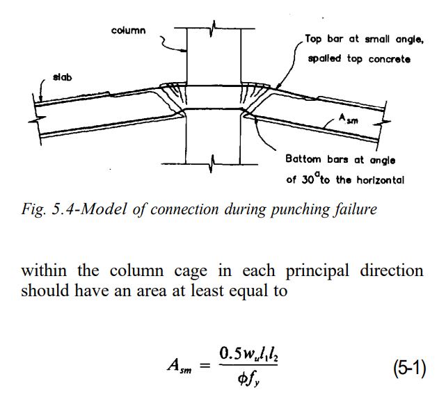
They make this statement about the latter: For Type 2 connections, the design loading conditions may result in general yielding of the top and/or bottom slab reinforcement at the connection. Experimental data[sup]42[/sup] indicate that under such conditions the punching shear strength may be reduced considerably below the nominal value of 4√f'c A[sub]cs[/sub] permitted by ACI 318, thereby reducing the margin of safety against collapse. Thus, minimum continuous bottom reinforcement as specified by Eq. (5-1) is recommended to support the slab in the event of a punching shear failure.


Glad we're on the same page here Koot.

Do you think there is any requirement of what ratio of reo bars go in either direction?? Could you justify putting all your reinforcement in one direction for a long, thin column - i.e if you had all, or majority, of the bars perpendicular to the longer dimension of the column and the slab was to punch, can you rely on your normal reinforcement to carry the slab loads coming from the shorter dimension sides to the extra bars in the other direction?

Our standard only mentions the amount of steel required and gives nothing on detailing requirements.
 
I do believe that the reinforcement can, and probably should, be placed about the perimeter in proportion to the length of the sides. For narrow wallumns, I often don't put any bars on the short sides. In addition to congestion issues, plumbing risers often need to be located at the wall ends.

 
Do you think there is any requirement of what ratio of reo bars go in either direction?? Could you justify putting all your reinforcement in one direction for a long, thin column - i.e if you had all, or majority, of the bars perpendicular to the longer dimension of the column and the slab was to punch, can you rely on your normal reinforcement to carry the slab loads coming from the shorter dimension sides to the extra bars in the other direction?

ACI 352 specifies that integrity steel should be provided (by their equation) in each principal direction. In other words, you cannot satisfy it by having half in one direction and half in the other.

[red]EDIT[/red]: See Section 5.3 of the link below for the integrity steel equation:


I think there has only been one revision since this version......and it didn't change Eq. 5-1.
 
WARose said:
ACI 352 specifies that integrity steel should be provided (by their equation) in each principal direction.

I've been treating that as a failure, on the code committee's part, to fully consider the range of application in modern concrete design. Given the mechanics underpinning the integrity steel provisions for punching shear, I don't see how one could fail to come to the conclusion that reinforcing running perpendicular to a wallumn would improve intended joint performance.

WARose said:
In other words, you cannot satisfy it by having half in one direction and half in the other.

That's gotta be a typo as the provision says specifically that having half in one direction and half in the other is how they want things. It's my and OP's proposal that putting 100% in one direction would suffice that is contentious.

 
Some additional thoughts:

1) I believe that, as the ratio of flexure to shear in a slab drops, the appropriate Vc value shifts away from 4SQRT(f'c) and towards 2SQRT(f'c). As such, given the usual loading arrangement sand proportions of transfer slabs, I suspect that the we're often overestimating Vc punching shear capacity.

2) When I'm dealing with wallumns, I actually make two modifications that I consider important:

a) I run most or all of the integrity steel perpendicular to the wallumn and;

b) For all but the shortest of wallumns, I concentrate the reinforcing near the ends of the columns where I expect punching shear failure to occur first.

 
That's gotta be a typo as the provision says specifically that having half in one direction and half in the other is how they want things. It's my and OP's proposal that putting 100% in one direction would suffice that is contentious.

That's not how I am reading it......although I may be misunderstanding something here. The provision (ACI 352) says:

5.3.1 Connections without beams-At interior connections, continuous bottom reinforcement passing within the column cage in each principal direction should have an area at least equal to [Eq. 5-1]....in which Asm = minimum area of effectively continuous bottom bars or mesh in each principal direction placed over the support,...

Sounds to me like 100% per direction (as per Eq. 5-1).

 
WARose said:
lthough I may be misunderstanding something here.

If you derive the expression yourself, which is a pretty simple exercise, I'm confident that you'll see it my way. The equation that you referenced is really targeting 1/4 of the total required punching shear capacity on each of four column faces.

 
If you derive the expression yourself, which is a pretty simple exercise, I'm confident that you'll see it my way. The equation that you referenced is really targeting 1/4 of the total required punching shear capacity on each of four column faces.

You may be right....but that's running with a assumed model. The commentary of 352 isn't specific enough to know exactly what that entails. Given that, I'd still have to run with the "each principal direction" approach they say.
 
WARose said:
You may be right....but that's running with a assumed model. The commentary of 352 isn't specific enough to know exactly what that entails.

It would be running with exactly the model that they provide in their sketch. No assumptions required. 0.5 = SIN(30). The rest is just accounting.

c01_xd3zwp.jpg
 
They still say provide Asm in each principal direction.....they say it in the latest rev too. So I don't think it's a typo. I might write ACI and see what they say on this.


It's not a typo. Asm in both directions gets you 100% of the punching shear resistance split equally over four column faces.

Fyyyyne... I'll do the derivation. After you tell me that you attempted it for at least 5 min on your own. KootK time is, unfortunately, cheap. But it 'aint free.

 
Thanks for the link WARose, does a much better job of explaining the clause than our standard does.

Would you care to explain what a Type 1 & Type 2 connection is?

 
Basically Type 2 is seismic. According to them:

2.2.2 A connection is classified as either Type 1 or
Type 2 depending on the loading conditions of the connection as follows:

(a) Type 1: A connection between elements that are
designed to satisfy ACI 318 strength and serviceability
requirements and that are not expected to undergo deformations into the inelastic range during the service
life.

(b) Type 2: A connection between elements that are
designed to satisfy ACI 318 strength and serviceability
requirements and that are required to possess sustained
strength under moderate deformations into the inelastic range, including but not limited to connections subjected to load reversals.
 
Ar Engineer

Have any of the people you are taking advice on for this actually read the AS3600 rule?

The rule in AS3600 does not define Asm as defined above. It defines the total area of reinforcement on the 4 faces, so nominally 1/4 of that reinforcement is required on each face. So the code has defined 4 * Asm!
 
Shooting from the hip as I'm killing time on phone and have read none of the reference documents, but is the 0.5 in the equation for Asm = (1/4)/(sin 30 degrees)? So the Asm needs to be in each direction as stated in the code (according to WARose).

Edit: on rereading, I think everyone is saying the the same total amount of reinforcement. It's the split between the two directions that's in question.
 
Status
Not open for further replies.
Back
Top