Continue to Site

Eng-Tips is the largest engineering community on the Internet

Intelligent Work Forums for Engineering Professionals

  • Congratulations cowski on being selected by the Eng-Tips community for having the most helpful posts in the forums last week. Way to Go!

Interactive Fixed Fastener / Projected Tolerance Demonstration 1

Status
Not open for further replies.

3DDave

Aerospace
May 23, 2013
11,247

Attached is an interactive demo of the fixed fastener case in Geogebra format. It has slide controls for the thickness of the tapped plate/hole depth, the percentage of the position tolerance that can be used for orientation, and the percentage of the location that remains given the amount of orientation. When the maximum is taken by orientation variation, none remains for location variation.

It plays by the Y14.5 rules, which don't take into account trigonometry, so it slightly under reports the effects of orientation variation. The name is a bit wrong as it doesn't deal with projected tolerances, but it was created to show the results of not using them.

I left creating the mating hole diameter to the user so that they could see how changes in the hole depth would affect the required hole size and, not dealt with here, the position tolerance of that hole in the mating part.

TruePositionProjected_tagl7e.png


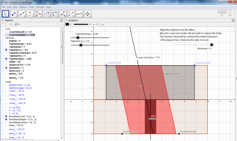
It also shows that position tolerances on holes in sheet metal should, theoretically, always have extremely small perpendicularity tolerances as well in order to gain the full benefit.

 
Replies continue below

Recommended for you

Also - just like the standard, this doesn't include any consideration for straightness, runout, or other coaxiality errors between the body of the fastener and the thread.
 
I see others are working to a similar goal - of course the name of the application makes it nearly useless to search for it, but contents shows the direction. It is software from Zbigniew HUMIENNY and Marcin BERTA.

4. Conclusions
The Annex A to the ISO 2692 standard gives only six examples of the MMR application with respect
to datums with MMR. This is not enough for most of industry people to understand well the MMR
concept when MMR is applied to datum or datums in a datum system.

Due to animated visualizations of the toleranced and datum features size and geometry variations it is
clearly shown in the application, that the additional bonus tolerance is directly available only when the
toleranced feature deviates from the MMC. The bonus tolerance when the datum feature deviates from
the MMC is virtually allowable rarely – only for specific configurations of a datum feature geometry.
The application Geometrical Tolerancing is an interactive powerful software that makes the complex
concepts of maximum material requirement easier to understand for designers, production engineers
and quality staff during vocational training. Due to the judicious use of animations the application well
supports vocational training as well as teaching at university and is appreciated by students.

That statement "This is not enough for most of industry people to understand well the MMR concept ..." seems borne out by the difficulty most industry people also have to understand well the ASME Y14.5 based on the explanations therein and the paltry examples given.

The paper even touches on perpendicularity and material conditions as examples to understand.

Another paper about this application:
 
Status
Not open for further replies.

Part and Inventory Search

Sponsor