Continue to Site

Eng-Tips is the largest engineering community on the Internet

Intelligent Work Forums for Engineering Professionals

  • Congratulations KootK on being selected by the Eng-Tips community for having the most helpful posts in the forums last week. Way to Go!

Interesecting Beam to Beam and Beam to Column Connection Details?

Status
Not open for further replies.

Redacted

Structural
Mar 12, 2016
160
Hi there,

I'm working on a reinforced concrete residential project where there will be a slab cast on top of a lintel/beam framing plan, as shown below :
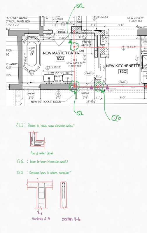
Structural_Element_Intersections_-_Copy_es1qgp.png


There are a few locations where there will be an intersection between structural elements and I am looking for best detailing practice for a residential situation. The floor loads are quite low.

For Q1 : The lintels will need to bear on the same corner support. If I connect the two lintels at the corner as shown in that detail, would I still be able to design the lintels as simply supported? Or would I need to design both lintels as pinned one end and fixed on the joined corner end (including fixed hogging reinforcement at the top)? Also I know that the detail I sketched is used for corner walls but can this also be applied to corner beams? Is there any guidance that someone can offer for this scenario?

For Q2 : Would someone be able to provide guidance on the best practice detail for concrete beam to beam connections. For this intersection, in addition to the vertical load from the secondary beam, would I also need to account for torsion (minimum eccentricity or something)? Is there any guidance out there for this sort of problem?

For Q3 : Would the detail I show be the preferred detail to connect a reinforced concrete column to a continuous beam with a u bar? Or is the preferred detail to have the column vertical bars extend with a 90 degree bending into and lapping with the longitudinal rebar in the beam with the minimum lap length?

Any guidance would be greatly appreciated.
 
Replies continue below

Recommended for you

Q1 - if they are monolithic then yes, I would be designing for a fixed connection
Most likely I would check both ways - bottom steel for simply-supported and the corner connection I would design hogging steel for a fixed-end moment
This likely conservative as it seems as if the beams are monolithic with each other but not with a column?
In which case the beam end fixity is torsional...this detail requires some serious thought and more info than we have currently - how does the floor integrate with this? What will the torsional detailing of the beams be?

Q2 - depends on your code but generally you have two options (under our code anyway, I assume the philosophies are the same)
In the general situation where you have a primary beam supporting a monolithically-cast secondary beam framing in then you can either design the primary beam for the full fixed-end moment of the secondary beam (this would be a large design torsion)
Alternatively, you design the primary beam for 'compatibility torsion' which is basically a lower level of torsion that represents that the secondary beam will cause some torsion in the primary beam, leading to cracking in the PB, leading to a loss of torsional stiffness in the PB, leading to low torsional demand in the PB

Q3 - bit confused by your sketch
But the philosophy for RC beam-column joints is to have the column bars go up to the top and return in with hooks and column stirrups continuing up to the top
The beam bars then run continuously through and the vertical beam stirrups stop at the face of the column
The 90 degree hooks are standard anchorage returns pointing into the column, they are not there to lap with the beam bars
 
Why use beams at all? The spans are small, so a five or six inch thick slab would seem adequate.
 
@Greenalleycat Thanks for your response so far. With regard to the Q1 location, in this corner, the beams will be resting on an existing CMU block wall (not monolithic with the wall), however, due to the bearing seat requirements, they would most likely need to have the intersecting corner of the two beams cast monolithically. I was initially thinking of having the floor slab tie into the beams either by designing the beam as an L or T beam. As for the torsional detailing, I haven't figured that out/designed that yet.

With regard to the Q2 location, thanks, what you have written is very helpful and I will most likely go with assuming that the full fixed end moment of the secondary beam is taken as torsion in the primary beam. Do you have any guidance on how concrete to concrete beams are generally tied in together? I'll carry out a torsional analysis on the beam to determine the torsional requirements, but it would be helpful to have a general idea. Is there also a way to alter the proposed framing to have no torsion at all (without putting in a column or wall support)?

With regard to the Q3 location, thanks and noted.

@BAretired, thanks that is a good point tbh. The beam to the left of Q2 will have a 9' tall hollow CMU block wall built on top with a roof. I'll need to check if a 6" slab can take that line load but if it can, it would definitely be more cost effective to get rid of beams where I can. I assume if only using a slab that I would need to incorporate embedded strong bands (extra reinforcement) above the openings to stiffen the openenings and minimize deflection?

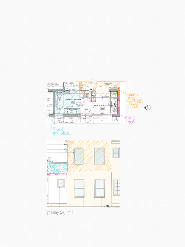
Due to the way the upper floors are framed out, I believe I may still need quite a few of these beams. For clarity I show the upper floor/slabs in the sketch below :

New_Drawing_14_1_-_Copy_ef8kpp.png
 
Normally the bars from the secondary beam will tie in and anchor across the full width of the stirrup cage in the primary beam
Personally, I would be designing for compatibility torsion in the main beam and designing the other beam as pinned, though with hogging steel at the junction
This is more conservative as otherwise you also need to figure out how to model the torsional stiffness of your concrete beam very accurately

Torsion in concrete beams is a real pig though as you will need a lot of extra steel
The exact amount if obviously code specific but I will assume it is conceptually similar
Our code requires a pile of extra stirrups immediately near the junction of the two beams, then requires tighter stirrup spacing along the rest of the beam
You also have to work out additional transverse and longitudinal steel reinforcement that is additive with what you need for flexure, so you have to put in new steel for that

To avoid the torsion, all I can really think to do is:
1) Pins do not really exist in concrete, so do not try to detail one to avoid torsion that way
2) You could seat one beam on top of the other - probably won't work with floor depths
3) Swap the secondary beam out for a steel beam. You'll still get a torsion from the eccentricity of the reaction but it should be much lower
 
Status
Not open for further replies.

Part and Inventory Search

Sponsor