Continue to Site

Eng-Tips is the largest engineering community on the Internet

Intelligent Work Forums for Engineering Professionals

  • Congratulations KootK on being selected by the Eng-Tips community for having the most helpful posts in the forums last week. Way to Go!

Interesting situation in Etabs dead load moment diagram

M

member 1218881

Guest
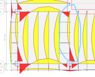
I am examining the moment diagrams of steel beams connected to reinforced concrete shear walls under dead loads. However, as seen in the figure, I connected two steel beams to a single point at the corner of the shear wall. As seen in the figure, the moment diagram of the marked beam under dead load appears incorrect. What might be causing this problem? Will connecting the beams with a "link" solve the problem?
jj
 
Replies continue below

Recommended for you

I don't know the answer to your question, however I am curious as to why are you moment connecting the steel beams to the shear wall, and why are you moment connecting the beams to the columns? Also, are the columns steel or concrete? They appear to be concrete. Perhaps there are regional differences in construction between where your project is located and where we do most of our work, but when we design steel-framed buildings with shear walls, the columns are steel. (Actually we usually use braced frames (versus shear walls) when using structural steel floor framing - but shear walls in steel-framed structures are not unheard of.)
 
I don't know the answer to your question, however I am curious as to why are you moment connecting the steel beams to the shear wall, and why are you moment connecting the beams to the columns? Also, are the columns steel or concrete? They appear to be concrete. Perhaps there are regional differences in construction between where your project is located and where we do most of our work, but when we design steel-framed buildings with shear walls, the columns are steel. (Actually we usually use braced frames (versus shear walls) when using structural steel floor framing - but shear walls in steel-framed structures are not unheard of.)
Under earthquake effects, the frame system of the building experiences a tipping moment of about 20%. In other words, under an earthquake, the shear wall does not cover all earthquake effects. I do it this way to make the design safe. That's why some beams (steel main beams) are constantly connected to the shear wall. These beams run between the columns and the shear walls.

Coming to your question, do you think it would be better to connect the beams jointly to the column and shear wall? However, in this case, I cannot create a frame system under earthquake effects.
 
It sounds like you are designing a fairly tall building. From my experience if you are trying to engage the steel framing with the shear wall core, you’ll need to do more than just moment-connecting the steel framing to the core at every floor. Depending on how tall the building is, we’ve added deep outrigger trusses at the roof (and perhaps other floors) to engage the dead load of the outer columns and reduce drift. Outrigger trusses will be more effective than moment-connecting the steel framing at every floor.

It sounds like seismic forces are governing the design (governing over wind). Is that true? It sounds like the seismic overturning moment (tipping moment) is putting net tension in the shear wall. Can’t you just design for that tension by adding reinforcing steel in the wall - or are you trying to control drift?

In any case I have strayed far away from your original question. It sounds like you are a younger engineer. I suggest that you ask the senior engineer supervising you for guidance. He’ll know more about the specifics of your project and the feasibility of various options. That engineer will be able to better answer your questions. It’s hard for me to give you answers without knowing more about the building, its location, design constraints, and the governing building code.
We can make the design safe by continuously connecting the steel frame with deep steel beams on each floor. It complies with earthquake regulations. Because it is a high-rise building, but not a building over 500m. İt is 250-280m high. In fact, the columns receive axial forces due to the frame effect, and 20% of the earthquake effects of the building are covered by the frame system. This is a situation we want. Additionally, my columns are concrete-filled steel embedded composite columns. In fact, the frame system absorbs some of the earthquake effects due to the tensile and compressive stresses that occur in the columns along with the frame effect.
 
Last edited by a moderator:
Just because it complies with earthquake regulations does not mean it's the most efficient design, as I think Cliff is alluding to. I agree with Cliff, though. Is moment-frame action not a poor bang for your buck in terms of lateral performance? All your lateral resistance is concentrated at the connection in conjunction with your column stiffness.

To answer your original question, is the restraint on the north end of the beam free to rotate? That would explain the zero moment at that node. Also, just another observation, if you're providing moment connections for all these beams to the shear walls, I would expect some negative moment at the ends. Unless you've pinned them to oversize the beams and then will get to the connections later.
Both ends of the beam are permanently connected against rotation. (There is no pinned) At the north end of the beam, the positive moment value shown in Yellow occurs at very small levels, around 15-20kN-m. If you pay attention, a situation similar to the moment diagram occurs in the continuously connected beam between two columns on the left. I'm wondering what could be the reason for this.
 
It seems like you are still try to learn quite a few fundamentals here. Both design fundamentals and Etabs fundamentals. I would have expected that a 250-280m high rise isn't the place for that.

But if this building is going to be constructed please let us know where so we can avoid it.
 
I agree with human909's sentiment. I think I may need to learn to read as well. Where do you say that this is not a real project?

I believe the small amounts of positive moments you are seeing for the left beam are the moments at the face of the column. If ETABS showed the moment diagram from node to node, you would see that there is 0 moment there. It appears that you have the north end of the two beams released to rotate which is why there is no negative moment at the support as you expected.
Both ends are not free from rotation. I cancel the offsets and check that the values are not 0.
 
Could you press (Ctrl + W), tick "end release" at section properties, Ok and show screenshot? To me the beam with negative moment have unreleased end (at least for major axis, M3 in ETABS assuming default local axis definition).
 
I agree with human909, most of us learn to crawl before we could walk. Seek guidance from a senior engineer in your office. What you are doing doesnt sound right. Hope you have a good mentor.

If you insist on making this 'moment' connection between steel beam and concrete wall, then you need to figure out how to make the steel connection work - I havent seen this done successfully as the bolt capacity will be low due to concrete failure.

Anyway, to answer your question. I suspect it has to do with how the walls were modelled and how you have done the mesh (automesh?), it may be that the beam is connected to the perpendicular wall instead of the parallel wall? not sure if you have out-of-plane stiffness on the walls.
 
Human909'a katılıyorum, çoğumuz yürümeden önce emeklemeyi öğreniyoruz. Ofisinizdeki kıdemli bir mühendisten rehberlik isteyin. Yaptığın şey kulağa doğru gelmiyor. Umarım iyi bir akıl hocanız vardır.

Çelik kiriş ile beton duvar arasındaki bu 'an' bağlantısını yapmakta ısrar ediyorsanız, o zaman çelik bağlantının nasıl çalışacağını bulmanız gerekir - beton arızası nedeniyle cıvata kapasitesi düşük olacağından bunun başarılı bir şekilde yapıldığını görmedim.

Her neyse, sorunuzu cevaplamak için. Duvarların nasıl modellendiği ve ağı nasıl yaptığınızla (automesh?) ilgili olduğundan şüpheleniyorum, kiriş paralel duvar yerine dik duvara bağlı olabilir mi? Duvarlarda düzlem dışı sertlik olup olmadığından emin değilim.
There is automesh on the wall. The out-of-plane stiffness of the walls is very low. Beams are defined at the joint point where two walls meet.
 

Part and Inventory Search

Sponsor