Continue to Site

Eng-Tips is the largest engineering community on the Internet

Intelligent Work Forums for Engineering Professionals

  • Congratulations GregLocock on being selected by the Eng-Tips community for having the most helpful posts in the forums last week. Way to Go!

Interference fit for plastic parts

Status
Not open for further replies.

fpnut

Mechanical
Feb 3, 2015
20
I don't have experience designing plastic parts that mate together, so I'd appreciate some pointers.

Basically I ordered plastic gas diffuser that will be pressed to fit, and I have made the inner diameter of the filter too loose, causing gas to leak from the mating surfaces.

Both diameters I have specified to be 10mm. In hindsight should have made diffuser ID smaller. Any general rule of thumb on interference fits on plastic parts - are they the same as on metals?
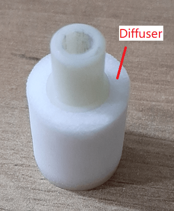
diffuser_m67dsj.png
 
Replies continue below

Recommended for you

What is the difference in coefficient of thermal expansion between the two parts?

Are they subject to creep? Even if successful initially, the joint may fail over time due to the high stresses involved in an interference fit.
 
The difference is about 35-130 x 10^-6/K (diffuser is HDPE, the inner part is PC).

In regards to creep - the parts will be interference fit, so probably yes.
 
Polycarbonate is readily bondable, even by chemical melt. HDPE is much more difficult. Is there a reason both parts can't be Polycarbonate?
 
Well the diffuser manufacturer (and most of them) offers it only from HDPE/UMWHDPE, so I don't have much of a choice here.
 
Oh, I know what the diffuser is now. Well, my understanding is that HDPE is creep resistant while polycarbonate is not. I hope I have the right terminology with creep. You'll see this in polycarbonate, if you install an interference fit screw such as a wood screw the plastic will eventually crack radically around the screw.

I would suggest investigating a barbed shape for the nozzle as the smaller lines of contact reduce the amount of force required to make a seal and the barbed shape will help hold the nozzle on place.

Also look in to the use of an adhesive instead of interference but this may add exponentially to the cost. See Scotch Weld DP8005 for an example.
 
It looks like the diffuser is foam/open cell? To get a good interference value you need two things. One is the elastic modulus and the other is the long-term-strain limit, both of which you'd likely have to get from the maker of the diffuser.

If you just go by elastic modulus then it might be 10-50 times what a metal interference fit would be, but since the long term strain limit is so much lower than most metals - I cannot guess without research what the interference reduction ratio should be.

However - as tugboat indicated, using a barb can offset both. Even if some area is overloaded there will be a neighboring region that isn't loaded and in between there will be some place that's just right.

I think I have also seen cases where the outside element has an undercut that matches a notch in the center part so that the loading is from shear due to pressure and the foam element only sees a short term strain during installation.

Which does bring up another aspect - how much strain is there in the diffuser from pressure? Is it possible to expand it like a balloon? right now you are seeing that pressure is not building as much as possible because of leakage from the interface/gap. This is where a shoulder/groove arrangement can help - particularly combined with adhesive as it gives the assembler a clearly defined location to apply the adhesive without blocking the rest of the foam surface.
 
I ended up making a silicone gasket cut out of sheets. Works fine for now while a redesign is being worked on.

Any recommended books on designing plastic parts?
 
ALWAYS start STEEL SAFE!

Your best guess on a press fit is never right. Start loose. You can always add plastic by removing steel.
 
Status
Not open for further replies.

Part and Inventory Search

Sponsor