Eng-Tips is the largest engineering community on the Internet

Intelligent Work Forums for Engineering Professionals

  • Congratulations waross on being selected by the Tek-Tips community for having the most helpful posts in the forums last week. Way to Go!

Interior Masonry Wall Bracing in PEMB 1

Status
Not open for further replies.

ThorenO

Structural
Jan 8, 2013
22
0
0
US
Hello,

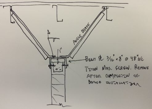
I have a partial height (15') masonry wall that I am kicking/bracing perpendicular to a Z-Purlin(s) in a low-seismic region.

In order to keep the roof deflection / or any expansions from producing a force at the top of the wall, does anyone have any ideas for a medium-duty connection detail for both the top of the wall and at the roof.

Will also span a cross member to engage an additional adjacent purlin for the loading.

Thanks for any feedback in advance.
 
Replies continue below

Recommended for you

I tried to do almost the exact same thing, except my brace was not at the top of the wall, but about 16'-0" up on a 20'-0" wall (to limit the span). To avoid any confusion, I posted the brace loads from my wall analysis.
OH MY GOD, THIS WAS A DISASTER. They added my brace loads, to their (wrongly calculated) wall out of plane forces. This in turn created huge anchorage loads. They complained about the brace incessantly. They never got it right, so one day when I was out of town, one of my guys got talked into removing the brace and having the wall span to the top of the building. I ripped him a new orifice, but the damage was done.
It's amazing that when the sales guys show up, they can do anything, but when you try it yourself, it's like re-inventing fire.

 
Capture1_t2bx7e.jpg


I like to debate structural engineering theory -- a lot. If I challenge you on something, know that I'm doing so because I respect your opinion enough to either change it or adopt it.
 
How about using two diagonal angle braces up to the roof members such that it looks like a triangle hanging from the roof? I like the idea of then connecting the braces to a short member between two roof purlins for load sharing. Then connect an angle or bent plate channel (with toes down) to the bottom of the triangle that allow the top of the wall to be braced horizontally but allows the roof to deflect without imposing load on the wall (ie slip connection).

I hope this helps!
 
We'll just call that substantial agreement.

I like to debate structural engineering theory -- a lot. If I challenge you on something, know that I'm doing so because I respect your opinion enough to either change it or adopt it.
 
Another thought: It is important to know whether the roof is a diaphragm or if just it floats (does not provide lateral support to the purlins). Depending on the amount of load that you are throwing into the purlins on a floating roof, there may be additional work to bring that load over to the girder lines or other bracing.
 
I like KootK's sketch, as well as Jike's write-up. One comment: be sure to allow a sufficient gap (shown as 1" in the sketch) between the top of wall and underside of bent plate. The PEMB manufacturer should be able to tell you the maximum design deflection.
 
Good idea on the braces, but be careful what you attaching to. Pre-engineered building Z-purlins are not stable laterally, so you are depending on the diaphragm capacity of the roof deck to carry the lateral loads to the rigid frames, but many PEMB's use standing-seam roof systems that are designed to move as the roof expands and contracts due to thermal stresses. Most of the clips allow around 1" of movement. So the question can be: Will you wall tolerate a 1" deformation at the top without problems? I have always had issues with masonry and PEMB's as they just aren't stiff enough unless the EOR requires them to be. Are there intersecting malls that could brace your transverse wall?
 
kcprofessor,
I think you are overstating the lack of stability of Z-purlins laterally. They do have bridging which braces the purlins together, and this bridging should connect to a stiffer element at the eave or ridge. After all, the purlins have to be stable enough to allow safe installation of the roofing. Even concealed fastener roof systems provide some stability to the purlins, otherwise the purlins could move rather than the roofing.
 
Drawing up KootK / jikes detail - In having a continuous bond at the top, can I span the wall further than 48" o.c. between braces?

And would including a bond beam at mid-height of the wall enable it to span further between braces.

Thanks again all!
 
The upper beam element capacity, among other things, will dictate support spacing. I don't see a mid height bond beam helping much in this regard.

I like to debate structural engineering theory -- a lot. If I challenge you on something, know that I'm doing so because I respect your opinion enough to either change it or adopt it.
 
The configuration of the bond beam and reinforcing will dictate how far it can span. I prefer the W shaped bond beams as opposed to the U shaped ones in that they prevent the bars from rolling together and both winding up in the center of the wall instead of one on each face. There might be a little more lateral capacity.
 
Status
Not open for further replies.
Back
Top